I thought it might be interesting for HGT readers to learn a little more about the various types of gas lighting burner with some reference to those commented on by Fred Starr in Issue 89 of December 2016, following the article by Reg Brown in Issue 88 of September 2016’s HGT.
(See note at the end for information on the Historic Gas Times ‘HGT’)
CLICK ON ANY PICTURE TO ENLARGE.
SOME PICTURES HAVE A SECOND ENLARGEMENT WITH AN X TOP RIGHT.
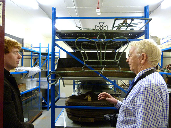
The first gas lighting burners were not much more than pieces of pipe with a hole or series of drilled holes. Indeed, the first demonstration of gas lighting was set up in London in 1807 by F.A.Winsor to use the gas produced in his retort in Pall Mall. The pipework was made and laid by Thomas Sugg and the burners utilised pieces of tube with a series of holes formed into shapes such as a crown. I imagine this was not unlike the one you can see in the picture below, taken in a store room in the Black Country Living Museum (BCLM) – along with our current Gas History Panel Chairman, John Horne on the right!
Naturally the size and visibility of the flame was dependent upon the quality of the gas and the pressure of the supply. Doubtless the very early gas was pretty unsavoury with little of what were to become known as the by-products actually removed. Indeed the smell had been a major irritant during the earlier demonstrations that Winsor had held in the Lyceum Theatre.
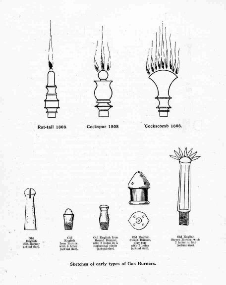
The illustrations above show many types of early jet, several of which carry very descriptive names such as rat-tail, batswing or cockspur as people attempted to achieve better performance. It became clear that flattening a flame by squashing the hole produced a flame that was more or less one-dimensional providing most of its light sideways from the flat side of the flame. As a fascinating clue to the age of some of these jets, one road that runs on from where the first demonstration mentioned earlier took place has the name Cockspur Street!
One of the significant problems of early metal ‘jets’ was corrosion, which could enlarge the size of the hole and increase the consumption. Lamps were very quickly known by the number of jets – or lights, (shortened to lt.) – and initially payment was related simply to the number of lights in use as opposed to the amount of gas consumed, which of course would require a gas meter.
Measuring the flow of gas was achieved in at least one of the earliest designs by passing the gas through a chamber carrying a ‘paddle’ half submerged in water so that the top of the paddle was pushed round by the gas flow and the paddle shaft drove a dial or series of dials to register the gas consumption that was measured in cubic feet related to the volume of the space between the paddles. For the majority of the life of gas metering, until relatively recent times, many gas meters continued to be known by the number of lights they could supply which was stamped on the side of the meter! The meters increased in size as larger flows had to be measured.
As time went on there were experiments in the use of different materials to use for the jets and William Sugg advertised the following around the middle of the 19th century:

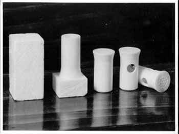
Steatite, mentioned in the page on the left (click to enlarge) taken from one of William Sugg’s booklets, is a naturally occurring mineral that was mined in India and sent rather like coal to Sugg’s Westminster works where it was machined on small machines:
The right hand photo shows steps in the machining of steatite from a rectangular block which itself was cut out of mined pieces.
The next feature to mention is controlling the gas to achieve the best illumination. William Sugg made a huge study of the waste of gas caused by poor burners. The quote from the Gas Referees report of 1871, printed around the fabulous matching pictures from the Sugg advert below, states that “The burners chiefly in use gave only one half the illuminating power of the gas and several tested by the gas referees gave one quarter the light of the gas.” Note, – Similar burners are still very largely used 1886 (The date of the advert).
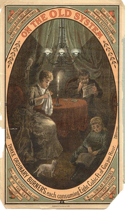

So, the majority of burners in use in 1886 only gave half the illumination possible. In this case William Sugg is promoting his Christiania burners. These burners are quoted as being “The perfection of Flat Flame Burners” and have both steatite jets and float governors. This latter device as its name suggests ‘floats’ (normally upwards) progressively closing the outlet. As the supply pressure varies so the float moves up and down providing a ‘smoothing’ to the flow and steadying the resulting flame.
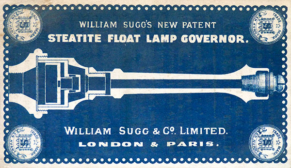
This is a street lamp burner, normally used vertically of course. It must have been easier to advertise this way!
You can see the float section on the left. The jet section on the right screws onto the float governor.
Whilst smoothing the flow improves the steadiness of the flame and doubtless the consumption, it is not until you control the pressure of the gas at the jet precisely and relate the pressure to the size of that jet can you guarantee to obtain a precise figure for consumption. With town gas manufactured from coal the pressure was initially achieved simply by the weight of the gasholder. The relatively small size of the mains and more local pipework meant that pressure could vary considerably. You only have to consider what happens at lighting up time when one lamp was lit after another and perhaps a new road had ‘come on stream’ – in modern parlance. The pressure on the lamps at the end of the line might be half that of the lamps nearest to the gasholder!
To solve this problem the gas governor was developed that uses a diaphragm to progressively adjust a valve against a set weight or a known spring pressure that modifies the movement of the diaphragm to provide a known outlet pressure. This then allows you to have a fixed jet, which will pass a known amount of gas to produce the perfect unwavering flame.
Whilst he spent a great deal of time on the open flame burner, William Sugg also developed the ‘Argand’ burner, well known in the world of oil burners and developed by M.Aime Argand. In place of a circular wick, the Sugg Argand has a circular, hollow, band shaped ring with a series of holes around the top edge producing a circular flame. Exactly as in the oil burner, air is entrained up the centre of the flame and, using a glass cylinder around the outside, air is also drawn up the outside of the flame. The result being a large perfectly aerated flame several inches long within the glass tube.
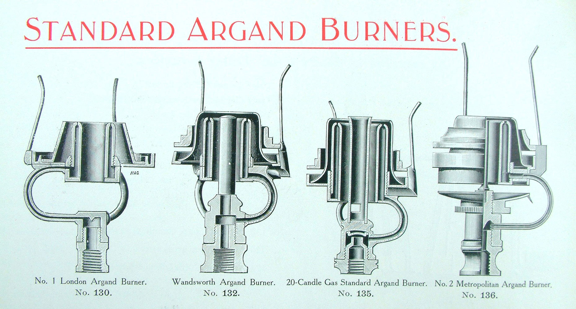
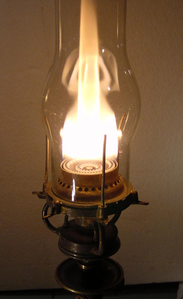
T he London Argand burner on the left of the group was the burner that the Gas Referees adopted in 1869 as the Standard Test Burner for the Metropolis and for which they stated “This burner of Mr Sugg’s excels all others.” The Argand photo on the right is a larger double ring burner version. (Photo M.Ara Kebapcioglu.)
For a long time William promoted the Argand burner over the flat flame burner, both of which were being produced at the same time. As competition increased it may have been that the clearly more expensive Argand was losing out and he switched loyalty.
The flat flame burners using steatite jets and float governors grew progressively larger as the demand for more light grew inexorably. The following photos show just how large these burners could be.
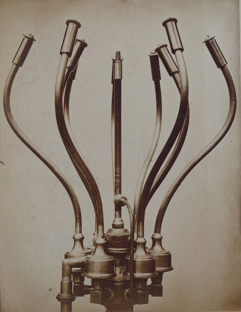
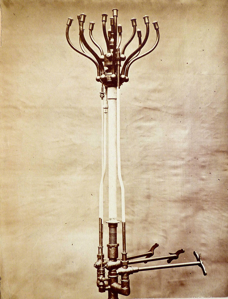
As you can see with the left hand burner there are 9 jets with a central pilot supply and on the right hand burner there would appear to be 8 jets on the larger circumference 4 on the inner set and a single jet in the centre along with a separate pilot which is aimed at the outer group. The central tap of three feeds the outer group, the further tap supplies the central group and the nearest tap, the central jet. A 4th tap controls the pilot taken off before all the others. This arrangement clearly would allow the lantern to be run at several rates from 13 to 12 to 5 to 4 to 1. I guess 12, 4 & 1 are the most likely with the single jet provided as an ‘overnight’ light where traffic is minimal. It may even be that the central single jet could be larger than the others for that purpose and not used when the other groups are in use.
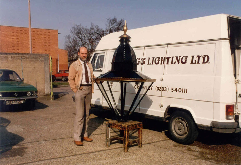
These burners explain the need for progressively larger lanterns and they really did get large! The surprising thing is that, despite the century and a quarter since these huge lamps were made redundant by the invention of the gas mantle, a few still survive. The Westminster lantern shown in the picture below with yours truly many years ago was found in Happy Valley, Llandudno and was returned there after refurbishment.
Interestingly, despite the invention of the mantle this did not immediately remove these magnificent lanterns from the street. The 1904 catalogue shows these lanterns with upright mantles and the 1915 list shows them with inverted mantles. The change of burner made a huge difference to the running cost and thus many users and local authorities would have been persuaded to make an economical change to the burner rather than to the whole lamp. In addition, the scale of the large posts on which these lamps were fitted meant that a smaller lamp would tend to look like a pimple on top! By this later date the shadowless lamps such as the Rochester and Littleton were developing and in due course the discovery of the superheater, used in conjunction with a group of smaller mantles, led to huge improvements in economical performance and the use of taller posts at which time the older bulkier posts could be scrapped.
The famous Windsor lamp, introduced in 1898 as I believe the first lamp specifically designed for use with the gas mantle burner, became particularly popular because, although the huge lamps were widely used in large cities, still the majority of town and village lighting did not warrant the gas usage and cost of the city lanterns. Here the lamps would have been similar in size firstly to the previous generation of oil lamps and then the earlier gas lamps with a single or double open flame. Thus, a lamp that made the big step into the improved performance of both economy and light output and could be easily substituted for the existing lamp had to be a sales winner. The 1906 catalogue proclaimed “Over 50,000 of our ‘Windsor’ Lamps are now in use”.
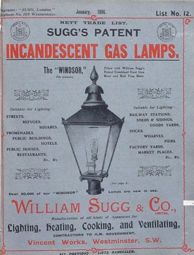
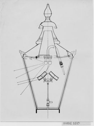
The Windsor shown on the front cover of the 1906 catalogue is shown with an upright mantle whereas the section drawing on the right shows a much later version with inverted mantle and a mirror reflector to improve directional performance.
The relatively slow adoption of changes is a fact of life. Sometimes it is because of the slow development of the change, incrementally improving along with high production costs for small volumes and sometimes it is a matter of perception and promotion that slows the acceptance. There will always be an overlap of designs with products and items that have a long service life. The shorter the life, the quicker the change.
When you work like we did at Sugg Lighting to cover nearly the whole gamut of the 200 years or so of gas lighting, you get a feeling for the development of this earliest aspect of what is known as the Utilisation side of the gas industry. Although of course at Sugg Lighting we were not the original William Sugg Company because it had been taken over by Thorn in 1969, we had the advantage of a generation of staff who had worked in Westminster and the archive of literature and historical documents to provide a link with the past and, incidentally, provide the details for this ever growing website www.williamsugghistory.co.uk
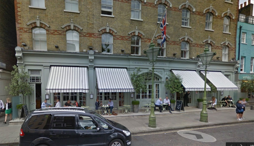
The two lamps in Charlotte Street that were mentioned by Fred Starr are rare examples of private street lamps owned by the Charlotte Street Hotel immediately behind. We were asked to provide a suitable remotely controlled open flame burner as a point of interest for the premises. The burner we made at the time has three open flames, a permanent pilot and an electric solenoid to be switched from inside the premises and as you can see in the picture below make an eye-catching statement in front of the building.
As there were no street lamp open flame burners we had previously looked at the past illustrations and at the available ceramic tipped jets. A lot of work had been done on jets at the time of conversion and we had developed a burner that could pass for an open flame by admitting a tiny amount of air to premix before the jet. Just enough to provide some retention and a little colour.
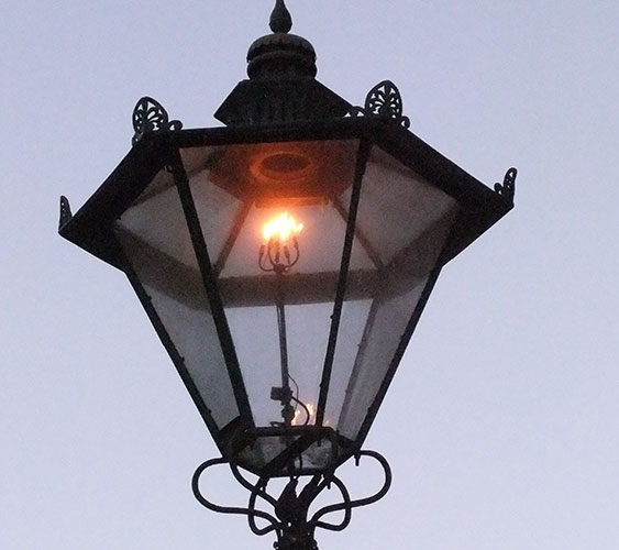
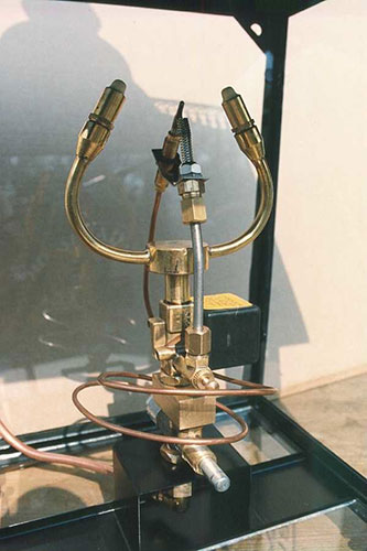
The left hand picture taken by Fred Starr in Charlotte Street shows the 4 lt burner alight. The right hand picture is a close-up of a 2 lt burner in the factory in which you can see the pilot and flame safety device with electric solenoid operator. The burners are formed inwards like the original ones to ensure cross lighting.
As with all gas lamps, maintenance was an issue that you ignored at your peril! The heat from a burner escaping through the chimney arrangement drew equal amounts of air in through whatever route had been designed to achieve this. In the early days the air in the cities could be hugely polluted with smoke from the burning of coal and the inside of a lamp would require cleaning frequently whilst the external surfaces could be dirtied by polluted rain. Open flame burners that were not burning cleanly would add to the dirt.
It is a fact that the vast majority of the population today has no knowledge of gas street lighting. Some may have come across bottled gas camping lights but would always assume street lighting to be electric. However, London still has some 1500 gas lamps, many of which are maintained continuously by a small group of lamp maintenance engineers uniquely employed within British Gas who are great enthusiasts for this world of the past. Several Royal Parks have been gaslit since Victorian times and many now have burners with solar charged timers, photocells and ignition made by Sugg Lighting. These are all inverted mantle burners that are maintained regularly and should burn cleanly with a bright white, incandescent flame. Buckingham Palace retains the gas lamps made by William Sugg & Co in 1910. The Houses of Parliament have original William Sugg 8 panel globes in New Palace Yard below Big Ben and one-piece ‘Barry’ globes along the front of the House of Lords at the opposite end, that were designed by Sugg Lighting at the end of the 20th century to match the appearance of the lamps shown on the original Barry ‘Pugin Gothic’ design drawings. (Some matching lamps on the other side of the road are electric versions.)
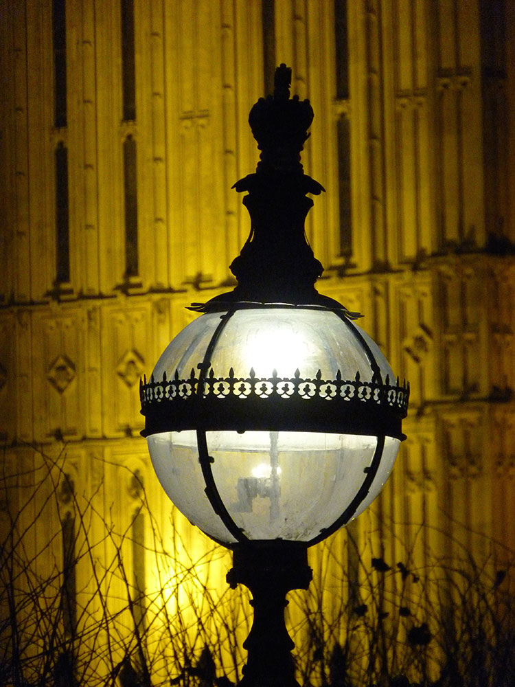
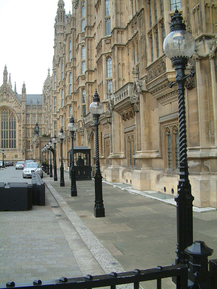
Original William Sugg 8 Panel Globe near “Big Ben’ and the Barry, Pugin Gothic Design Globe from Sugg Lighting outside The Lords.
A final comment on the mantle and incandescence. Whilst Bunsen had invented the device that carries his name to produce a high temperature, it was a chance discovery by Welsbach using a bunsen burner that heated some spilt chemical that incandesced. Thousands of experiments with dozens of chemicals including the rare earths, produced a chemical mix which provided 100 years of high lighting performance better, many say, than the modern chemical alternatives.
The Historic Gas Times is produced by the Gas History Panel of the Institution of Gas Engineers four times a year. ‘To subscribe, please visit www.igem.org.uk/HGT’. Annual Subscription £8.00 (UK only) Overseas Rates (for 4 issues) £15.00 Sterling (Air Mail) Or Sent via email £6.00 World-wide. Please make your cheque payable to: IGEM History Fund. Please post to: HGT Subscriptions, IGEM Membership Dept., IGEM House, 28 High Street, Kegworth, Derbyshire DE74 2DA. For any subscription enquiries Please telephone the Membership Department on 0844 375 4436, during o ce hours.
3 responses
Outstanding ρost but I ᴡas wondering if you could write a litte more on this topic?
I’d be very grateful if you could elaƄorate a little bit more.
Thanks!
Do you read The Historic Gas Times (HGT). I am afraid I have too many other tasks to add any more to the article but HGT has lots of other interesting articles and stories. Details on how to subscribe are at the end of my blog.
Thanks for finally talking about > The Development of Gas
Lighting Burners – originally written for the Historic Gas Times
in 2017 – William Sugg & Co < Loved it!