(This is an element of ‘Lighting‘) The one feature of all gas lamps, indeed of burning gas in any appliance, is the production of heat. In the days when houses were entirely lit by gas and especially with open flame burners, something like a third of the heating of the house came from the gas lights. In fact many users were very happy about this because the heating of houses was largely by coal fires and then by gas fires (see the Heating section). This meant that the temperature varied enormously throughout the house and without the gas lighting providing some heat elsewhere, the draughtiness would have been considerably worse. Having indicated an advantage of heat from the gas fixtures it is also a significant problem, especially in public buildings in which a large amount of gas would be burned to provide sufficient light. Refer to the Street Lighting section to see just how large the lamps became in order to survive the enormous heat of the burner. The answer, or at least a means of providing a solution to the problem was to connect the lamp to the outside air in the form of a chimney. This would then form a passage for the hot products of combustion and, by linking this to the hot air in the room the whole fixture became a means of ventilation, hence the name ventilating lamp. As lighting fixtures are always high up where the temperature is the highest they could perform exceedingly well in their guise as ventilators and, because in many cases in public buildings they are very large, a surprising number of these fixtures still exist and one or two are still in use! Of course, the Victorian designers revelled in producing fabulous designs for these imposing fixtures which would often be the focus of attention, for instance, in the ceiling of an equally decorative theatre .
See below the sunburners for the ‘Updraught Ventilators’
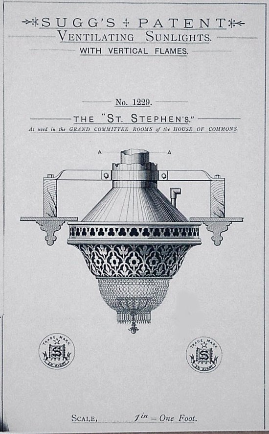
Ventilating Sunlight as used in the House of Commons
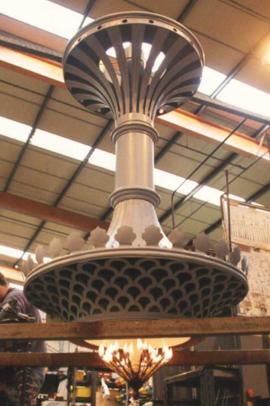
Original Sun Burner refurbished and fitted with electronic ignition in the Sugg Lighting factory prior to being installed in one of the buildings of the new Scottish Parliament.
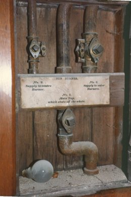
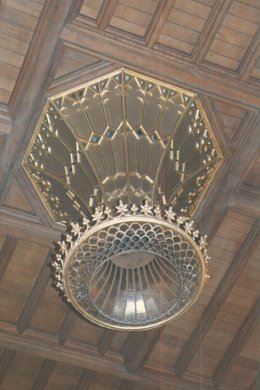
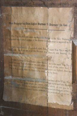
I took these pictures in the 1980’s of this magnificent Sun Light in a building near Redhill in Surrey. Not only does it clearly show the mica reflecting surface which surrounded the burner and allowed some light upwards but it appeared to be fully installed – apart from the burner – complete with a small cupboard with the controls and the instructions pasted to the inside of the door. The central tap has the legend “No.1 Main Tap which shuts off the whole.” On the left it says “No.2 Supply to centre burner.” On the right it says “No.3 Supply to outer burners.” You can see that taps 2 & 3 both have small parallel bypass taps which would allow a small amount of gas to pass even when the main tap is turned off. This would be set to keep the burner running at a very low level so that either the centre or outer burners could be turned on remotely without having to apply a light. I imagine that the main tap was turned off during the summer when the light was not used. The instructions are headed “Gas Supply to the Sun-Light Burner in Landing”. Unfortunately there was a printing error which nobody ever corrected so that the the text partially repeats and each sentence is not completed. It is possible, however, to interpret the lighting instructions although the last paragraph in talking about turning out the Sun Burner indicates that there is a damper which is opened by the pressure of the gas. It is, unfortunately, not clear as to where this damper is located but it could either be in the flue or possibly in the pipework to prevent an explosive gas-air mixture forming as the gas in the pipe leached out with the taps being a long way from the burner.. This problem was dealt with in other lighting equipment and is discussed under CCS controls. It specifically applied to the use of manufactured town gas.
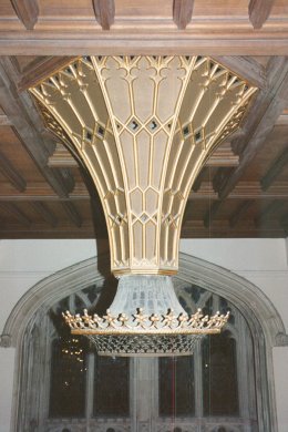
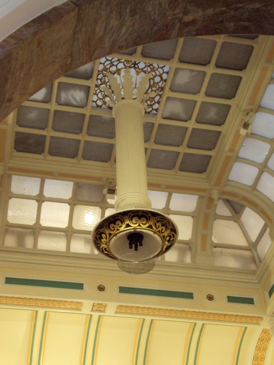
This magnificent Sun Burner can be seen by any visitor to the Victoria and Albert Museum in London, along with a whole row of identical fixtures at the right hand end of the first floor. Although not operating on gas they have been carefully electrified to show many features of this type of fixture. You can see the ventilation slots in the ceiling support where the hot air at the ceiling level is drawn in and up by the temperature of the central ‘flue’ heated by the gas flames. They have used the design of the fixture to hide some ‘uplighters’ which illuminate the superb ceiling – a feature that would not have existed originally.
————————————————–
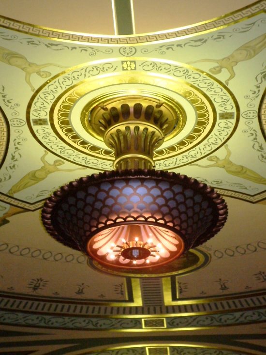
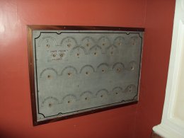
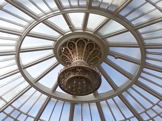
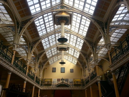
Several of these pictures were sent to me in January 2010 by my old Sugg Lighting colleague, Melvyn, who had been visiting the Birmingham Art Gallery – as he knows my interests – sad really! However they do show two classic sun burner installations which are still in their original state and position and can be seen by anyone in the area. The control panel indicates just how many fixtures were controlled from this central point and how the building was designed around the lighting. More recently in 2013 I was asked to advise on the safety of these ‘unused’ appliances and I have added two more pictures providing a close-up of the highest mounted fixture and a general view taken by installation, maintenance and gas consultant Chris Warren who was visiting to discuss the possibility of inspecting these amazing fixtures.
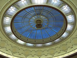
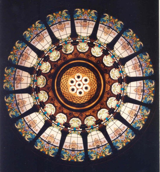
The Gaiety Theatre on The Isle of Man has this fantastic decorative glazed dome, below, with a 7 unit sunburner set in the centre. Converted to electricity by Sugg Lighting in the late years of the 20th Century it was part of a major refurbishment of the theatre.
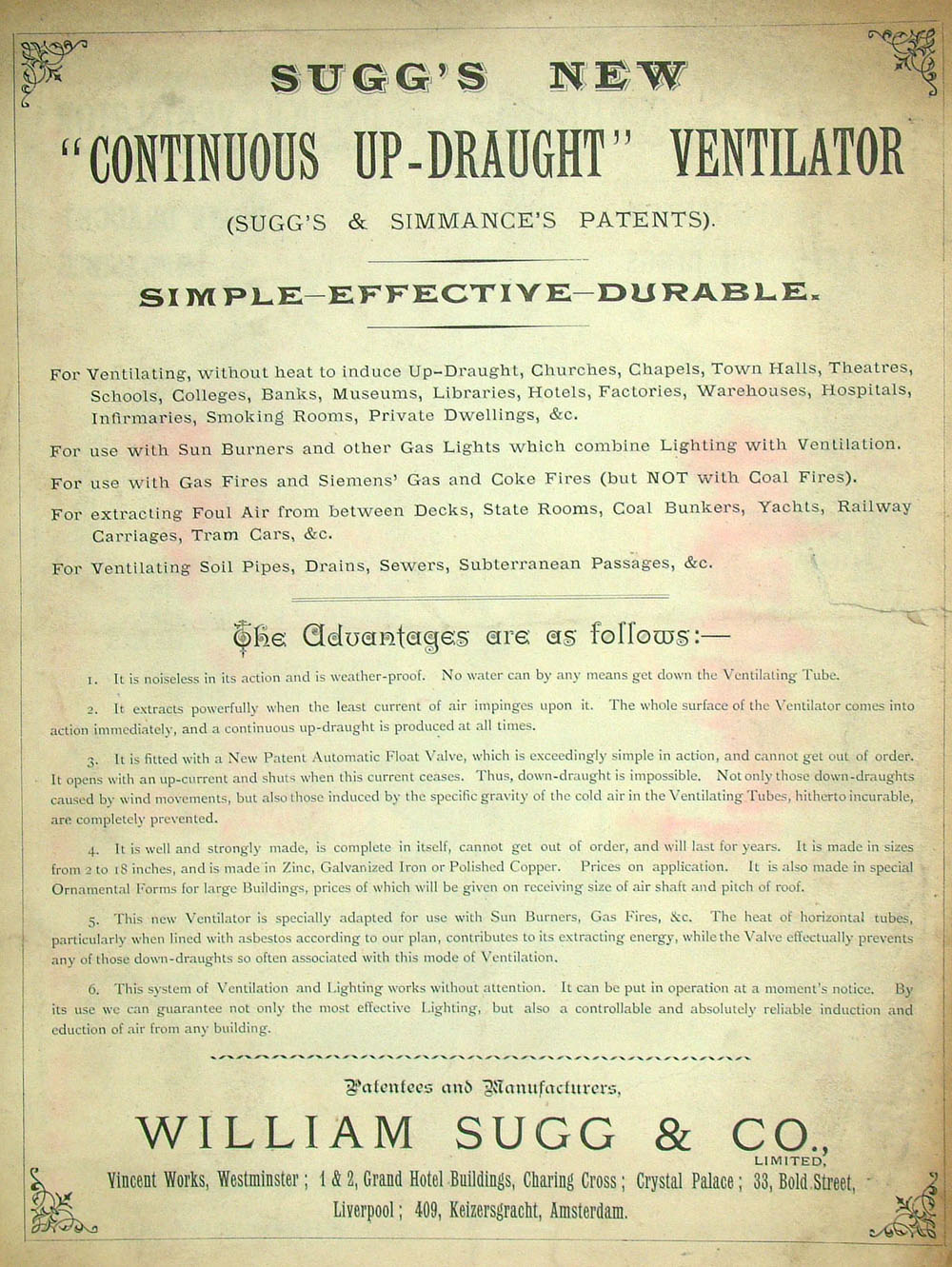
Continuous Updraught Ventilators
Ventilation as applied to problems other than Sun Burners.
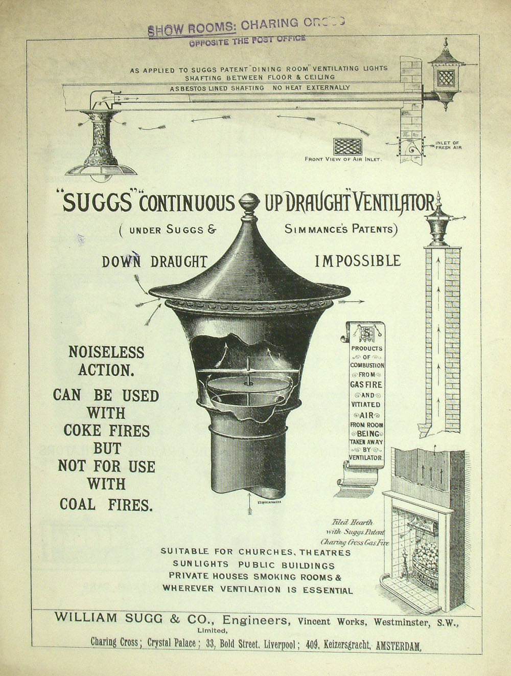
Although the second ‘application’ indicates that the system was used with sun burners it is clear from the illustrations, however, that the device stops down draughts.
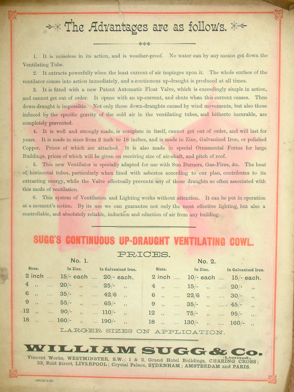
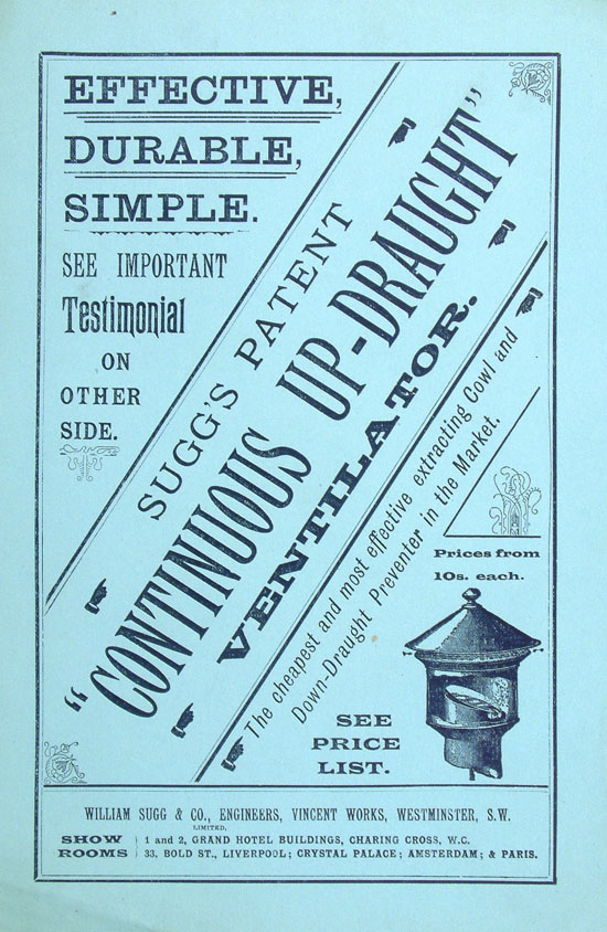
The Continuous “Up-Draught” Ventilator. Catalogue Pages Around 1880.
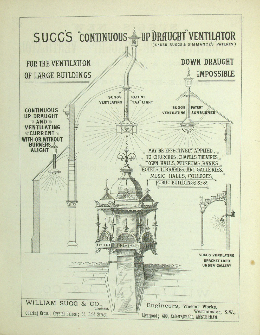
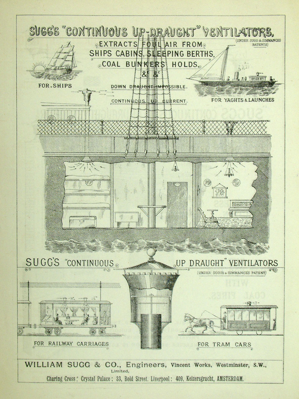


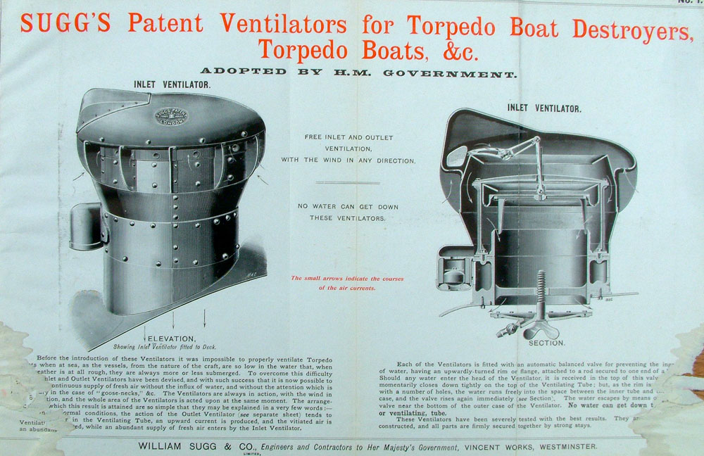
It would seem that William Sugg became well known for his expertise in the ventilation of his gas street lighting so that they burned perfectly steadily in high wind conditions. Following the development of the sun burner he then applied his inventive mind to several ventilation problems one of the most unusual being that of the ventilation of ‘Motor Torpedo Boats’. You can see in the text below that these boats were ‘so low in the water that when it was at all rough they were more or less submerged’. For this application he devised not only extract but also inlet ventilators which you can see in the following illustrations. Click to enlarge top right to read text. Catalogue 1905.

UNDER CONTINUOUS DEVELOPMENT Copyright © Chris Sugg 2006-13 https://williamsugghistory.co.uk/?page_id=14#top or Back to ‘https://williamsugghistory.co.uk/?page_id=67’
21 responses
Very interesting. Dover’s Maison Dieu has 3 sunburners, 2 are situated in The Connaught Hall and the other is in the Council Chambers, I’m not sure if these sunburners were installed by your firm, if you have any record I would be very interested in knowing about it. I look forward to hearing from you.
Thank you, John, for your comment. As you might imagine there were several, if not many, manufacturers of sunburners or sunlights and they were manufactured over a relatively short period of time as a means of both lighting and ventilating the larger public and occasionally private, buildings. They were almost always built into the structure which provides a clue to their date and of course the reason for their survival. I am afraid there are no sales records that far back and I can only refer to some original Sugg literature for clues as to the manufacturer. The only other route is usually related to the building records which sometimes survive, especially with important local buildings, or even the records of the local gas undertaking. I am sure that it is an area that would warrant far more research than I have had time for.
As they are usually very decorative, I would be happy to add any pictures to the site, as it may well help others looking for answers on this very Victorian product. An indication of size is always helpful. Chris.
Hi! I’m currently trying to work out the lighting history of Manchester Free Libraries from 1852-1879. For a few years they switched from gas to hydro-carbon burners and then back again to the old gas system. The City Gas Chandelier and Furnishing Ironmongery Establishment, Showrooms 15 Piccadilly, Manchester persuaded them to change to Hydro-Carbon, following the example of the Athenaeum. There are references throughout the Minutes, reports etc to Sunlights and their dangers so I presume these could have been used with both hydro-carbon burners or gas. Is that correct? Really struggling to understand all this so any info would be appreciated. Great to find the gorgeous photos and history on this site – thanks!
Lucy
Hi Lucy, interesting project! Not far away from you in January this year they were refurbishing a building in the Whitworth Art Gallery and uncovered some sunburners which had been completely hidden by a false ceiling.I am no expert on hydrocarbon oil gas but I suspect it would need heat to get it started which could prove difficult that high up. You can’t do it at a distance and send it down a pipe without it condensing back to a liquid. The only gas I know that was used as an alternative to Town Gas would have been acetylene which can be generated outside the building and piped just like coal gas and produces a nice bright white flame. It is however, mighty dangerous by comparison. Perhaps you could find out something from the Athaneum records. Town gas was poisonous – hence putting your head in the oven – but unburnt gas at ceiling level would have gone up the chimney with all the heat from the room. Perhaps the splendidly named ‘Establishment’ was doing it for ‘commercial’ reasons of their own or maybe there was a threat to the price of gas. Do let me know if you come up with anything that we might add to the website for future researchers. Chris
Hi ChrisHi Chris, Thanks so much for the reply and great information. It’s really interesting about the Whitworth. I’m writing a biography of Andrea Crestadoro, inventor and Chief Librarian of Manchester 1864-1879. The minutes, letters etc trace his problems over lighting and especially his annoyance with the ‘Establishment’ – John Rigby and Son. The various complaints suggest oil was used with the gas but I don’t have the expertise to work it out exactly. It looks as if there were oil holders placed under gas burners. Each holder had to be filled with a pint of oil and the oil was constantly splashing over onto the desks below.
I’m happy to send the draft of my lighting section for you to take any info that you think might be useful. Please contact me directly for this, Lucy
Hi Lucy, I may have found the answer which is worth making generally available hence this reply! (Drawn from and quoting Dean Chandlers book ‘Lighting by Gas’) “In 1878 Mr James Kidd introduced a device for enriching coal gas in situ by means of which the light-giving power of the flame obtained from a flat flame burner was greatly increased.”
“Although this was not the first attempt to enrich coal gas it was more successful as it employed compressed naphthalene in the form of sticks or balls rather than naphtha. Kidd’s “Albo-Carbon” Light as it was called consisted of a copper vessel positioned in relation to the gas flame in such a manner that when the gas was burning it was heated sufficiently for the contained naphthalene to be vaporised. The gas was led through the vessel and in its passage through it, hydrocarbon vapour was added to the gas.The burner recommended for use with the Kidd lamp was a Bray flat flame, consuming 3 cubic feet of gas per hour, which ordinarily gave a light of about 10 candles. After the gas was first lighted it required several minutes before the effect of the carburation was seen. The light then became very bright and the illuminating power was of the order of 30 candles.”
I have some more detail but you can see the principle and clearly the problem would seem to relate to the use of naphthalene. It seems that it exists normally in the form of light, filmy, crystals which made it difficult to charge the vessel. This was overcome by melting the naphthalene beforehand and running into moulds in the form of candles or spheres, in which form it was easily inserted in the container through a small hole provided for the purpose. For lighting on a large scale a carburation vessel was used which was independently heated by a small supplementary burner and from this vessel the pipes were taken to convey the gas to the various gas burners.
“One of the first installations of the ‘Albo-Carbon’ Light was at the Westminster Aquarium which resulted in being able to reduce the number of Bray burners from 500 to 200 which provided more light than previously. The system consumed 4.1/2 lbs of naphthalene costing 1s.6d. (7.1/2p) per 1000 cu feet of gas enriched and resulted in 40,000 candle hours being obtained from the gas which without carburation would have yielded only 14,000 hours.”
In conclusion it may well be that John Rigby & Son were trying to emulate the enrichment of coal gas with their own system using something other than naphthalene which resulted in incomplete vaporisation with some of the liquid dripping onto the desks below. Chris
Hello Chris. Just a footnote to your mention of ‘Kidd’s Albo-Cabon Light’ I have a mint example of one of these curiousities. Came complete with naptha sticks, some already in the vessel, burner, and even a long mahogany-handled key to turn it on/off. Kind regards, Steve
Thanks Steve & well done for reading through the comment string! If you would like to send me a picture of your rare ‘curiosity’ I would be happy to add it to the page and refer it on to the relevant comment. You never know who might like to see it! The website is slowly adding ‘items of interest’ rather than just Sugg and if that adds to the usefulness of the site, so much the better! Regards, Chris
Hi,
I am working in an academic paper about the Reform Club london. I found out that the burner in the morning room was produced by Sugg’s. I am trying to find out about the large sun burner an the saloon installed in 1852. It may have been custom made on the design of Charles Barry. Do you have any information about it?
Hello Fernando – interesting project! 1852 is pretty early for records and my Sugg literature on sun burners is some 30 years later although it has to be said that the same products were often manufactured for many years. Each of these sun burners will have or have had a control panel similar to those shown on the site. I have never seen one with the Sugg name but that doesn’t mean they don’t exist! As I say in the article these devices were so much part of the fabric of the building that they are often left in place even when they had become redundant. It would be more than likely that if you know that one sun burner was made by Sugg the other would be too. I imagine that you have access to early records at the Club which is where you are most likely to find relevant correspondence and invoices. I do have drawings of other Sugg sun burners if you would care to send me a picture of both of these devices I will see if there are any similarities. Apart from the actual device there will always be a ‘chimney’ and a roof cowl which can provide clues although these parts are more likely to have been removed in subsequent alterations. I would appreciate being able to add specific details to this site as part of the history of these relatively short-lived devices and of course the Sugg business. Thank you in advance for any further information.
Hi Chris,
Thank for answering my enquire. I have been looking on the club archive for the invoices but not luck yet. How could I sent you photos, I have try to attached here but it seems not possible.
I will send you an email from my home email address that you should be able to add a picture to. Thanks, I look forward to seeing it. Chris
/Users/asaxer/Pictures/iPhoto Library/Masters/2014/09/06/20140906-122608/2014-02-17 14.39.33.jpg
/Users/asaxer/Desktop/ReformClubfiles/sections reform /18 PART II morning room /ligths/IMG_4562.JPG
I’m currently doing research for the ventilation of westminster abbey, and i found out this page about the sunburner on the ceiling. i would like to know more about it for the ventilation use. Lookinf forward for ur reply thru email soon;)
The page you found carries a lot of information about this means of ventilation and how it works. Westminster Abbey is of course a gothic building some 700 years old so would never have been ventilated this way. I think perhaps you are having me on! I am afraid you will have to refer to the architect, Christopher Wren!
Hi Chris,
I am an architect, working on the restoration of the market buildings at Smithfield, where we found a large light fitting, which appears to be a historic sunburner. I know by written descriptions that the architect, Horace Jones, used sunburners for his other projects. I would like to show you photos of this object and try to establish if it is what we think, and also if it is by any chance a Sugg design. Let me know if there is a way to contact you.
Georgia please send the images to ch***@*******************co.uk and I will see what I can do to help you. Regards, Chris
Hi Chris, we are an architecture firm that has just finished an historic preservation/restoration project where we based the design of the new chandeliers off of the Sugg’s sunburner photo above from the Victoria and Albert Museum. Historic documents revealed that the building used the lamps but there were no surviving images. We are hoping that you might allow us to use this image to show the inspiration for the lighting design? You can see the results of the lighting design here – https://dietzarch.com/portfolio/chicopee-city-hall/
Hi Ashley, I am glad that you found some inspiration in the designs of the early sunlights and I would be happy for you to use one of the images with a reference to William Sugg and hopefully the William Sugg History website. The room looks ready for business! Regards, Chris
Am staring at the sun burner in my lounge. The room was a council chamber. Currently it has a light bulb attached to it!! I am thinking some small leds around the circular base to try and ape a burning glow rather than a light bulb.
The electrified sunlights in the Victoria & Albert Museum show what can be achieved. It is a little misleading because there is no uplighting from the real gas fired version but that might not worry you! Send me a photo when you have it finished.