(This is an element of ‘Lighting – Burners‘)
To jump directly to Steatite, click here
The open flame burner is the first type of gas burner developed to burn gas and in its simplest form was purely a hole or a series of holes in a pipe. The well known illustrations below indicate the range of very early burners with descriptive names, some of which are still used to describe flame shapes today. One, ‘Cockspur’, even gave its name to the street which runs between Pall Mall and Trafalgar Square and a Court which runs off this street, both adjacent to the location of the demonstration of gas lighting by Winsor in 1807 for which Thomas Sugg made and fitted the supply pipe.
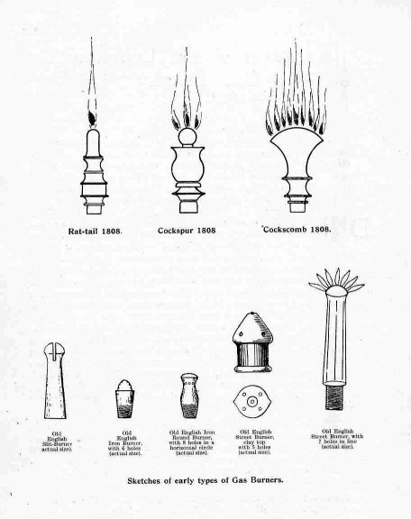
Page 82, Dean Chandler, Lighting by Gas
The problem with simple ‘holes’ is that the size of the hole controls the amount of gas that passes through it and, apart from making it the right size to start with, should it enlarge through rusting or wear, the amount of gas will increase and the flame will get bigger. The by-products of the production of gas from coal included many noxious and corrosive substances. The complete removal of all these substances would have been impossible in the early days of manufacture and there was in any case always an amount of liquid – largely water – in the supplies. The variation in the amount of gas supplied to a ‘consumer’ was naturally of ultimate concern to the early gas producers because they were paid according to the amount of gas assumed to be burned by the number of ‘lights’ at any particular location.
It was thus a considerable incentive to find a method of recording the amount of gas that was being used in any premises and thus the gas meter was a very early development. When William Sugg advertised in the very first issue of The Builder in 1847, the advert claims amongst other things that they were “Makers of Improved Patent Gas Meters”. (See also the Technical Section)
Waste of gas and inefficiency also exercised the fertile mind of William Sugg. According to Dean Chandler, William ‘realised the great importance of two fundamental principles upon which the efficient burning of gas for the production of light depended’. Firstly from Sir Frederick Branwell that it was essential “to keep the flame hot” and secondly from Professor Tyndall that it was “necessary to keep the velocity of the gas issuing from a jet slow enough to allow the proper combination of the oxygen of the atmosphere with it”. William reasoned that the use of an incorrodible, insulating material which could be accurately produced would provide much of the answer. The result was his steatite flat flame burner of 1858 which is included in the following illustrations from William’s book.
(Details on the production of steatite components is included further on).
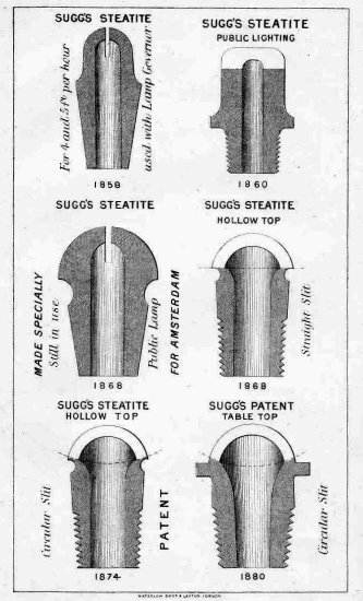
Modern Street Lighting, 2nd edition by William Sugg 1887
Whilst this first steatite flat flame burner was made entirely of steatite the major use of the material was as the tip or jet or top of a myriad of burners largely made of brass . The photograph below is of a surviving box of steatite tipped burners.
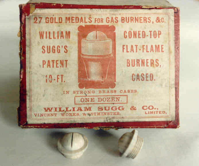
An Original Box of Coned-Top Flat Flame Burners, c.1880.
The burners shown, whilst in the same box are, however, not ‘cased’.
There is an excellent picture of a Sugg Governor Burner with the item as illustrated on the box in a set of burners in the ‘Collectors Item’ of Ray Tye. You can also see both of these items on the burner display cases below.
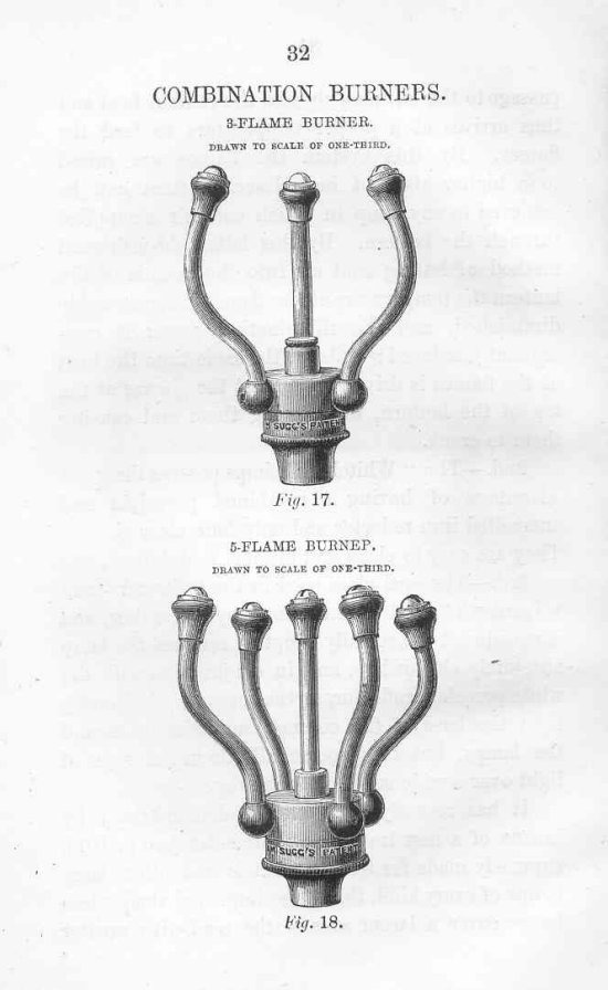
The woodcuts below from ‘Modern Street Lighting’ by William Sugg show these table top burners in use in 3 lt, 5 lt and a 10 lt burner for the Greenock Lamp. These latter lamps were developed for the lighting of docks which were busy places in the later years of the Victorian age with ships carrying goods to all parts of the Empire needing to be loaded and unloaded at all hours, day and night. This burner is provided with three supply connections allowing it to be operated with 1 lt, 4 lt, or 10 lt.
The steatite tipped burner provided the perfect long term answer for the resistance to the high temperature and corrosion to which all burners were subject and also the means of shaping the flame to provide the best light. The 30 lt burner below must be one of the largest lantern burners produced.
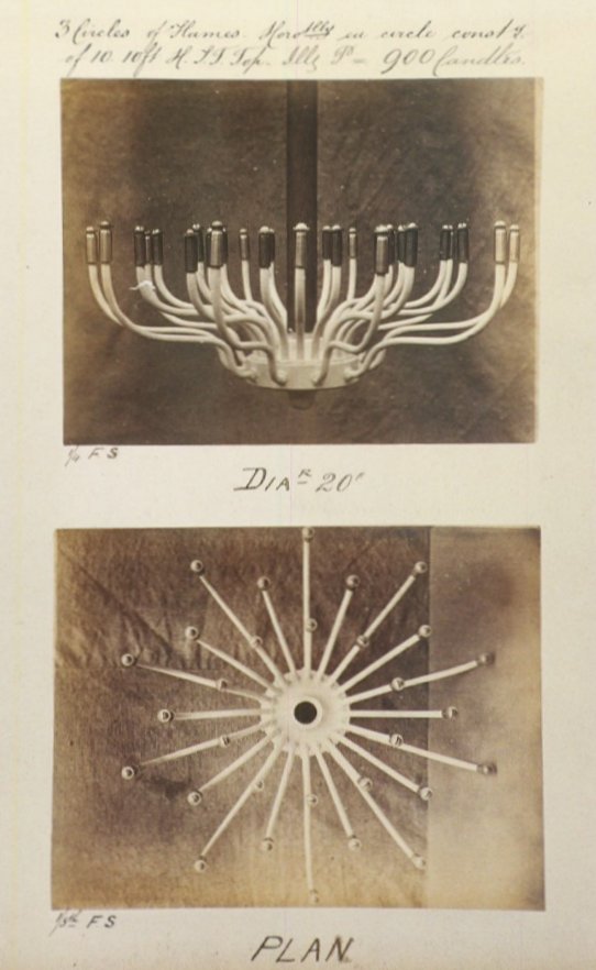
30 lt Open Flame Lantern Burner, 20″ Diameter.
Consists of 3 circles of 10 Table Top Burners.
Illuminating Power of 900 Candles.
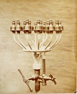
These two street lighting burners show, on the left, as far as I can count, an 18 light governor burner with a separate lever cock controlling the inner ring of burners that must have been made for a short but wide lantern.
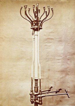
On the right is a burner, similar to the Greenock burner woodcut above, clearly made for a tall lantern. It has a bypass pilot, a manual control for an outer ring of 8 flame burners, a separate manual control for an inner ring of 4 flame burners and a third manual control for a single, central flame. The levers on the right hand burner do not have holes for chains and have very long extensions presumably to project through the side of the lantern.
Having controlled the flow of gas by a fixed size and /or shape of orifice the other essential aspect of the supply of gas is the pressure at which it is arriving at the orifice. Clearly a much larger flame will be produced by a higher pressure and vice versa.
The variation in pressure in the street gas main must have been a real problem for the engineers of the day. There were so many unknowns, such as the capacity of the pipework which was being continually extended to increase the number of street lamps, the means of storing the gas, the time at which demand would rise, the temperature, the phases of the moon etc, etc. Every time a lamp was lit it would affect the others. The result was a very uneven supply and gas flames that varied in performance from minute to minute. If the jet has been designed to provide a specific size of flame for the maximum performance at a specific pressure then the incorrect pressure will fail to provide what is expected. If the gas is being sold on the basis of a price per ‘light’, the consumer – or vestry – will either pay too much for a small flame or too much for an inefficient large flame, whilst in the latter case, the gas company will also lose because it is supplying too much gas.
William Sugg concluded that the only answer was to combine the burner with a governor and designed a series of street lamp governor burners which are illustrated on the page below.

Page 57, Modern Street Lighting, 2nd edition by William Sugg 1887
Quoting William’s text from ‘Modern Street Lighting’ (second edition 1887) opposite this illustration above, he says:
“The series of lamp governors invented and manufactured by the author arranged chronologically, show the progress made in these articles during the past 26 years. Many of the 1859 and later patterns are still in use, having been in constant work for over a quarter of a century. Upwards of 3 millions are in use in various parts of the globe”
You will notice that all of these burners make use of the steatite jets. The governor burner was one of Williams earliest inventions and combined with the steatite burner was a very important step in the international reputation of the company.
Steatite Jet Test &/or Demonstration Kit.
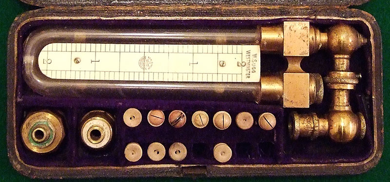
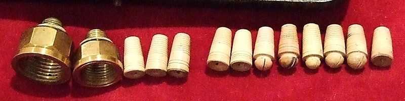
The following photos were sent to me by Bill Whiteley in 2017. He has a collection of old instruments ‘though very few to do with gas’. When he sent me these pictures I was intrigued because the actual set was not one I had come across before. It was however clear what it included and how rare it must be because the jets are all open flame and include two adaptors for attaching them to either 1/8″, 1/4″ or perhaps 3/8″ BSP gas pipe thread. This would allow the jets to be tested or demonstrated whilst at the same time checking the gas pressure using the included ‘U’-tube manometer. There are several different types of jet which you can compare with the ones shown in the second illustration in this section above from Modern Street Lighting of 1887.

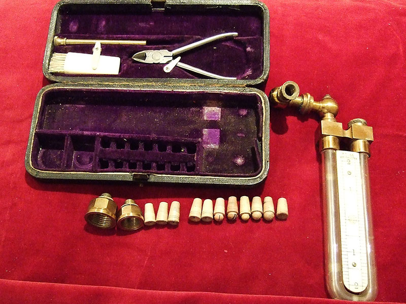
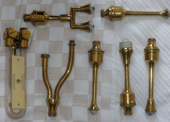
Open Flame Street Light Burners Boxed Demonstration Set.
Complete with ‘U’-Tube Manometer and Adaptor Piece to allow Burner to be lit whilst also checking the gas pressure

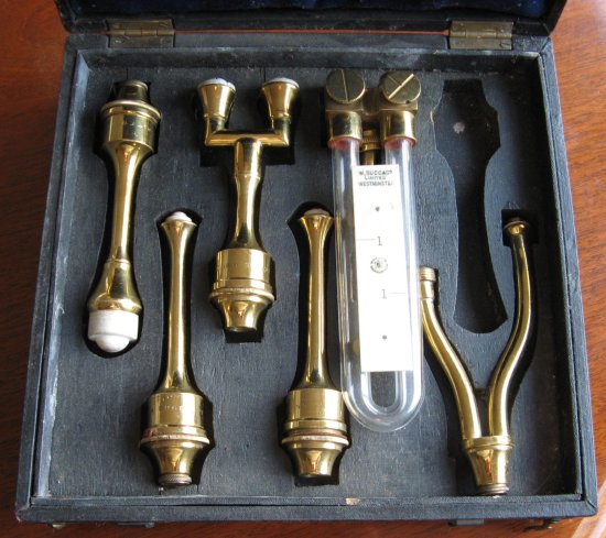
This is a rare ‘collectors item’ found by a fortunate relative in the loft of a house in London after the demise of the owner, who had worked in the gas industry for a lifetime. I believe it is a representative’s display box because, although we know William insisted on a high level of excellence, padded cases seem a little over the top! You can imagine the impression this would have made on a prospective customer, as the top was swung open to reveal a highly polished set of table top governor burners along with a neat U-tube water gauge for testing the gas pressure at a lamp. These are obviously governor burners of the 1881 pattern which was manufactured for many years.
AND THEN I was contacted in early 2011 by an auction enthusiast who had bought the apparently identical set, see below, near Cambridge from a local house clearance without knowing what they were. Of course they are branded and so led him to this website and then to me. Whilst I would not count myself as a true ‘collector’ I really wanted to see these burners ‘up close’ so I now own the set – which, as you can see, is short of one burner – anybody got one?! The significant point about looking closer at these burners is that I am now totally convinced that they were a practical display set. Each of the burners has a different rating, from left to right they are branded 15ft, 5ft, 20ft, 2ft – and then the missing one? The ‘Y’ branched item on the right is an adaptor that allows the water gauge to be fitted on the lower arm whist a burner is fitted on the other. It would thus be possible to accurately set up any or all of the burners and even to check the performance and suitability of any one size in a particular lamp or under a specific set of lighting conditions.
AND THEN!
In May of the same year – 2011 – I was once again contacted by an eBay seller who had found ANOTHER one of these display boxes, this time at auction in Bourne End near Marlow in Buckinghamshire, probably from a local house clearance. It seems very likely that when the open flame burner was superceded following the invention of the gas mantle these display boxes also became redundant. Being such attractive items the reps and maybe others who held them felt disinclined to throw them away and simply kept them as a reminder of the past. Doubtless their children and maybe later generations held them until there was no-one left who knew what they were! And then they went to auction!
Having secured a second – and full set – I was thus able to compare them and also confirm the rating of the burner missing from the previous set as being 10 ft. Just to clarify this specification, these ratings are in cubic feet of gas at 1 inch of water pressure which is why the ‘U’ gauge in the set has just a single 1″ scale. As you can see in the illustration below, the ‘U’ gauge is slightly different but it still has only a one inch scale.
Sales of governor burners were worldwide. The promotional literature advised
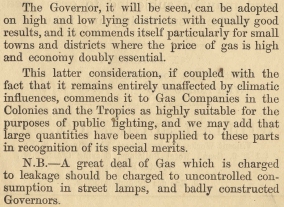
So clearly, burners went to the ‘Colonies’ and the ‘Tropics’.
Perhaps some of these demonstration cases went too!
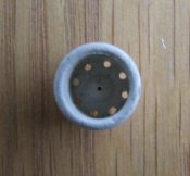
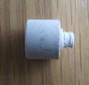
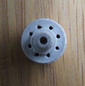
Steatite
As there have been many references to steatite, at this juncture it might be helpful to illustrate the production of this useful material. Mined in India it arrived in Westminster in chunks, a bit like coal. The photos below illustrate the production of steatite items. The burner parts and jets were turned on small lathes driven by cat gut from the overhead shafting which ran throughout the factory, originally driven by steam and later by electric motor. The items would have been fired in an oven becoming extremely hard and durable. In addition to applications for gas lighting, the steatite shop in later days produced huge numbers of insulating items for the electrical industry until eventually overtaken by other more economical ceramics.
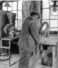

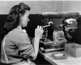
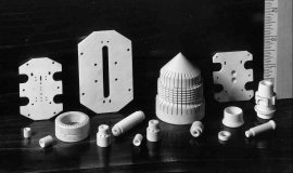
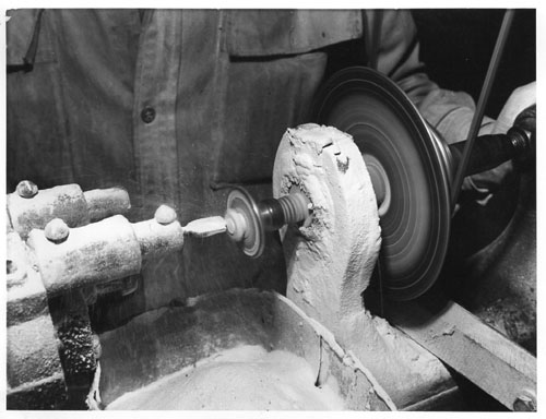
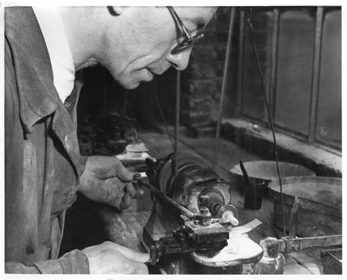
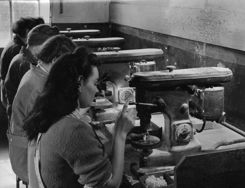
Steatite Component Manufacture
As can be appreciated, the amount of steatite dust or powder that was turned and cut off the thousands of parts was considerable. William, in classic style – and in much the same way as waste from cereal production is turned into compressed biscuits – came up with an extraordinary product. By compressing the steatite powder into metal tins he was able to offer a product that was called “Pearly Queen Tooth Powder”! Clearly abrasive, I suspect that it worked extremely well but I would also suspect that too much brushing could well remove not only the tartar but also the enamel! One of these tins, unused, was presented to a retiring director in my time in the business, so somewhere there may just be another very rare collectors item!
The steatite ‘Carpenter Jet’ was widely used as a ‘byepass’ or ‘pilot’ and is surprisingly good even on natural gas – if you can find one!
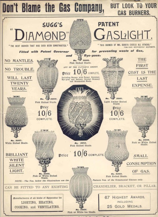
You will note in this advert the comment ‘No mantles No trouble’!
UNDER CONTINUOUS DEVELOPMENT – PLEASE TRY AGAIN LATER
Copyright © Chris Sugg 2006-13
2 responses
You probably have seen the drawing in this patent but just in case … –
https://patents.google.com/patent/US245579A/en?q=SUGG&sort=old .
Thank you, Peter, I know that William Sugg held a number of US patents but I had not seen this one. It is quite a complicated approach and relies on two steatite sleeves sliding perfectly together. He seems to have been concerned about sudden increases in gas pressure making a single piece sleeve slam against the outlet and cause the flame to go out. This invention has a form of two stage closing which he claims will prevent this by slowing the flow in a more controlled fashion. These burners were particularly important when gas was very largely used for lighting only and the pressure could vary enormously at lighting up and closing down times. Thank you for the link which I am sure others will be interested in. Chris