(This is an element of ‘Lighting – Street Lamps‘)
The Regent, Littleton & Rochester Family of Gas Lights with Variants, including
a Guide to the Recognition and Refurbishment of one of the most important and widely used Families of Gas Lights ever produced.
This range of gas lamps starts with the Regent in 1908 and in one form or another was manufactured in quantity by William Sugg & Co. Ltd for half a century with one of the largest ever orders received following the end of the Second World War to replace those damaged in London during the blitz. Spares and small quantities of lamps continued to be made right up to the 1960’s, particularly for the railways that had been a regular and substantial user. Following the takeover of the original Sugg Company, there was a relatively short gap before the Rochester lamp became a stalwart of the Sugg Lighting Company, formed with a group of ex William Sugg employees. Whilst becoming an electric fixture in its new guise, one model in particular was reconstructed for gas. This, the large Upright Rochester may still be seen, particularly in parts of Westminster, London, a very apt location considering that Westminster was the home of the Sugg business from its foundation in 1837.
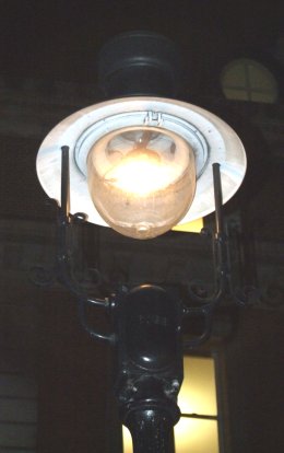
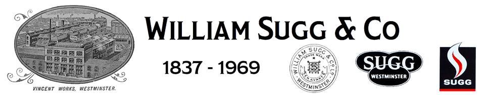
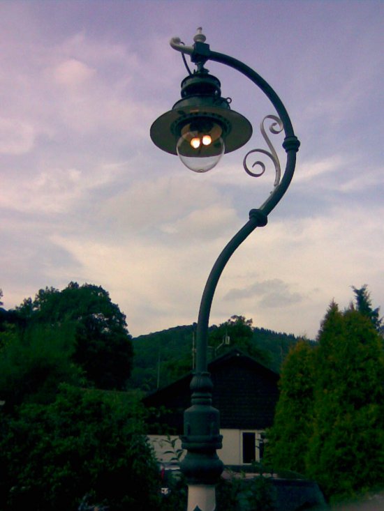
Pictures of Rochester’s running on gas in Covent Garden 2007.
The one on the left is a new ‘Upright’ model made by Sugg Lighting and the two on the right are originals on very substantial brackets that probably supported larger lanterns back in the 19th C.
————————————————-
Position of the shadowless lamp in the history of gas lighting
Prior to the introduction of the suspended shadowless style of gas lamp that is considered here, there had not been much progress beyond the traditional box shaped lantern for the lighting of streets. From the early days of gas at the end of the 18th century, the open flame batswing or fishtail type of flat flame burner provided a very modest performance when placed in these all-glazed box shaped enclosures which were designed purely to protect the flame from the wind and weather. The use of a gas flame was only one step from the wick of the oil lamp and in both the flame flickered and threw what light it could largely sideways and upwards, often leaving sufficient of a shadow close to the lamp post to disguise the presence of a footpad ready to jump out on the unwary.
William Sugg was very aware of the shadow thrown by the ribs of a conventional frame lantern but whilst the flame burned upwards it was difficult to arrange the burner so that it did not produce shadows. A range of decorative interior fixtures known by the name ‘Cromartie’ was designed by his son David Sugg in the 1880’s which did achieve a shadowless result. However, the burner design did not allow for the multiple high performance use necessary for street lighting and it remained a highly decorative interior fixture. See Lighting/Interior Lighting/Cromartie.
Effect of the introduction of electricity
Once the introduction of the electric arc lamp had galvanised the gas industry into action in the last quarter of the 19th century and the almost impossibly fragile gas mantle had developed into a more practical lighting device, we begin to see how these developments influenced the design of a new type of light.
The inverted mantle was introduced in 1903 but it was not until 1908 that the Regent lamp was introduced as the first of the new breed of “shadowless” lamp. Never before had such a large candle power been obtained from a wind and weather proof lamp of such small dimensions. The Regent utilised the large No 4 and No 6 size mantles on separate gas and air regulators. It was not until 1911 that the superheated cluster was introduced. This cluster was commonly known as the Littleton type and thousands of Regent lamps were converted from No 4 size mantle to the Littleton principle. The Littleton lamp is thus a superheated cluster version of the Regent. More information on the development of these burners in Lighting/Burners.
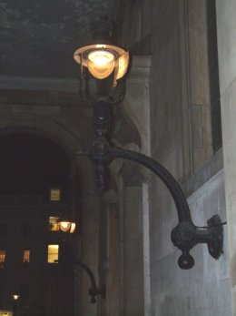
The Regent may well have been inspired by earlier suspension lamps such as the Chertsey and the Newark illustrated below which utilised upright mantles within a glass globe suspended below a circular shade reflector.
The Newark exhibits a number of interesting features some of which are used on later developments. Access to the twin upright mantle burner and the inside of the glass for cleaning is achieved through a section at the bottom of the globe which hinges down. The body is wind and rain proof which allows for remote control with a second supply pipe providing a permanent pilot. The ‘Mercurial Seal’ is designed to prevent gas leaching out of the pipework when a remote tap has turned off the supply. The problem that this overcomes is two-fold. Where several lamps are being controlled together there is no delay and they all light together. The more significant problem that the seal eliminates is related to air mixing with the coal gas back up the pipework. Under certain circumstances this mixture can reach explosive levels such that when turned on, there is explosive ignition within the mantle which is thereby ruined. Those readers who experienced ‘towns gas’ manufactured from coal will also have experienced the ‘pop’ frequently heard when lighting the gas on a cooker or fire.
The controls developed for the Rochester & Littleton lamps include the DCD or Distant Control Device and the CCS – or Central Control System which both provide a similar measure of control over gas leaching out of the system and air replacing it.
Surprisingly, at first sight to the 21st century mind, these ‘old fashioned’ designs continued to be manufactured alongside the Regent. This, however, ‘hedges the bet’ that the new design will be taken up whilst also ensuring that customers of the earlier design do not feel upstaged. Imagine what would happen if a car manufacturer introduced a new model whilst leaving the old one in production!
——————————————————
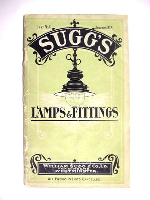
The List 11, for January 1912 “Lamps and Fittings” catalogue below, illustrates the Regent on the cover with the same body shape as the Littleton. You need to look closely to see two of the multiple gas and air regulators and also the large mantles.
The confusion over names due to the series of developments of the same lamp
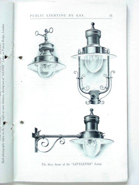
The confusion over the names of various generations of the Littleton lamp is well illustrated by the page, above, taken from a lecture by J.W.Lofts, a Director of William Sugg & Co., at the Technical College, Huddersfield in November 1924.
Both the ‘upright’ and ‘wall bracket’ models have bodies much closer in style to the Rochester then the earlier Littleton, itself more recognisable in the suspended form in the same illustration.
The retro fitting of the later technology
A major effort was made in due course to convert street lamps to the superheated cluster of small mantles. By 1912 hundreds of thousands of lamps were being converted all over the world because it had been demonstrated that the Littleton principle both developed the greatest illuminating duty from the gas consumed and reduced the maintenance cost of mantles. The fact that the traditional square lanterns continued to be sold, despite their obvious disadvantages compared to the new lanterns, is almost certainly because of the huge numbers of 8 ft to 10 ft posts which would also have needed to be replaced to take best advantage of the extra power available. Bear in mind that the levels of acceptable illumination meant that a 14” Windsor would frequently have only 1 No.1 mantle and a 16” only 2!
Recognition
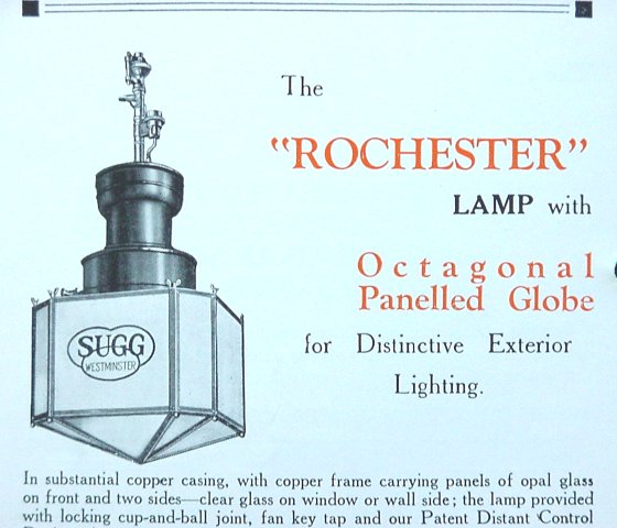
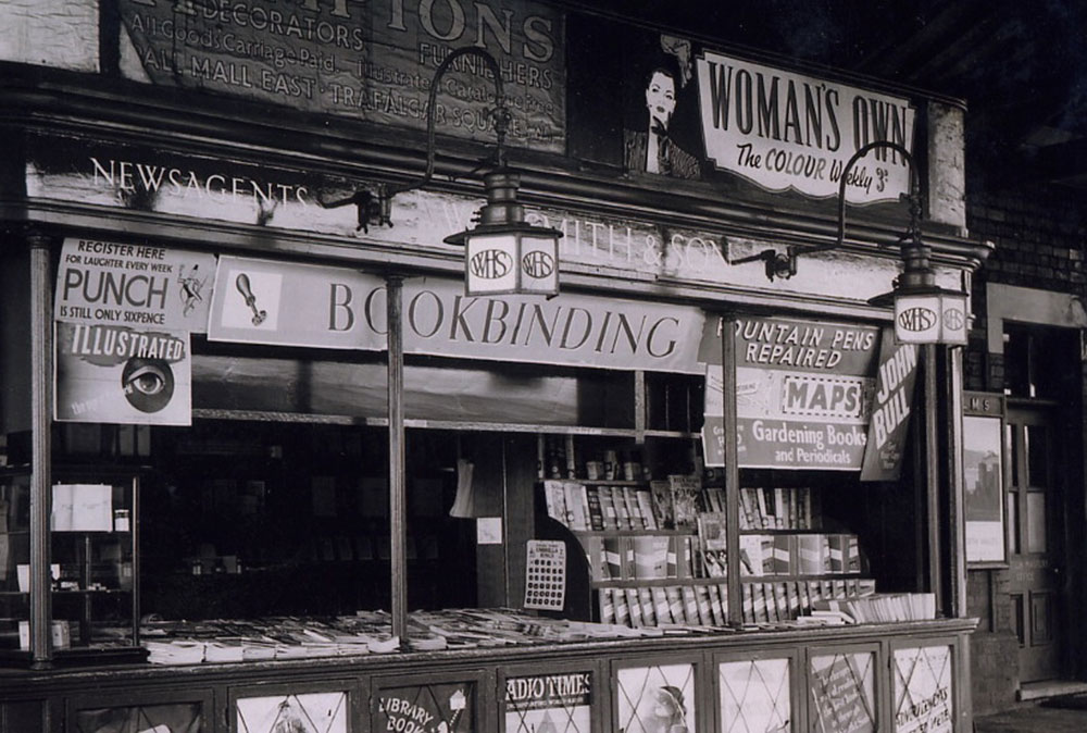
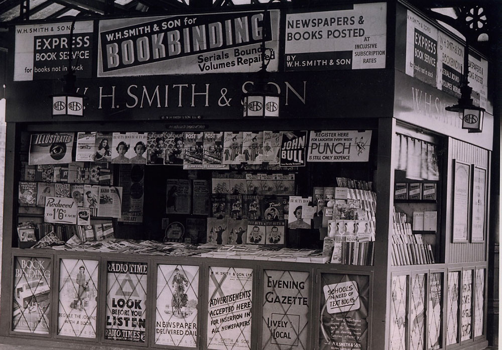
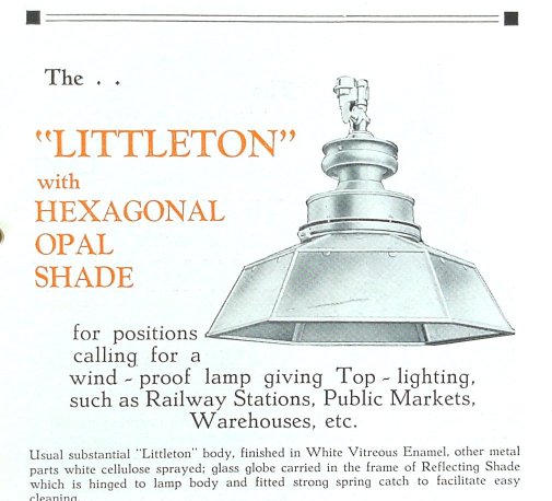
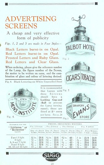
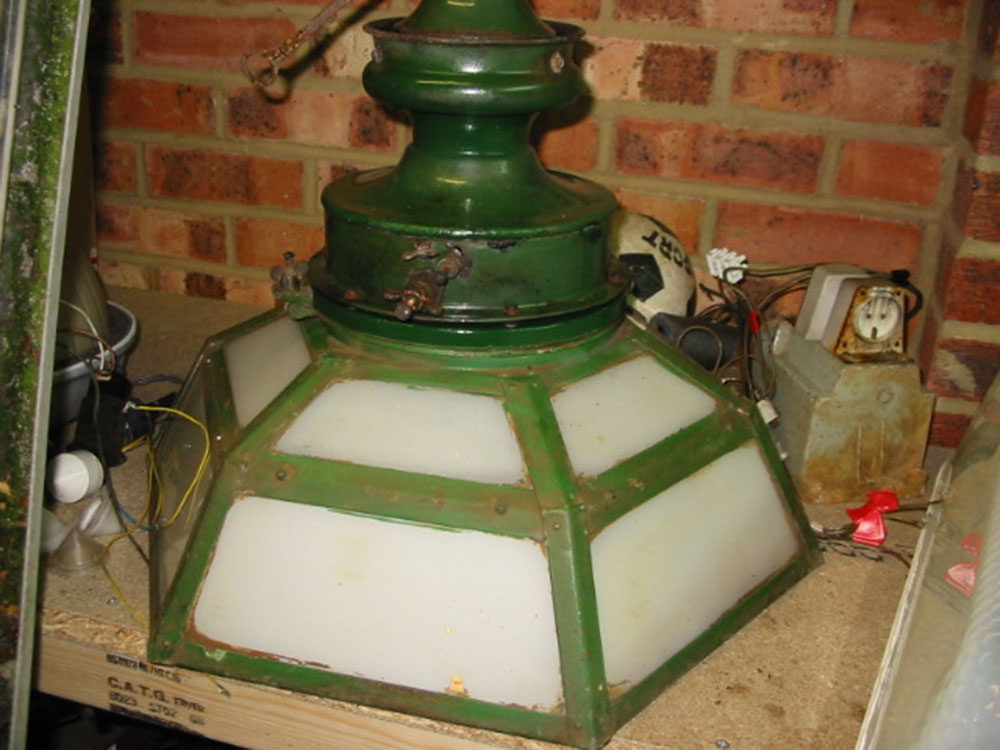
Although it is possible to recognise the basic models quite easily there are many variations on the theme which can provide a moments uncertainty! The reflector can vary in both diameter and shape and there are even models with parabolic reflectors and others with hexagonal opal glass shades. Name indicators attached to the edge of the reflector are very rare because they were made of glass. Enamelled reflectors that hang down vertically from either side of the reflector, following the shape of the globe, are more likely to have survived. More unusual are “squat patterns” in which the body height has been dramatically reduced as they say “for low headways”. The “Holyhead” is a small wall bracket mounted Rochester without a reflector designed for “porches, verandas, passage ways, latrines, etc”! It has an overall height of just 12” and the projection from wall to centre line is only 6”. In the 1930’s the art deco mood produced chromium plated Littleton’s with octagonal panelled globe and Rochester’s with a similar octagonal globe which was frequently used as an advertising sign – at the extra cost of 9/- per panel. The railways even used a suspension model with an opal Perspex shade in later days.

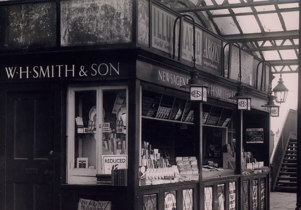
Below are three views of WH Smith station kiosks with Rochesters having WHS advertising signs- click to enlarge. (Pictures from David Redfern)
A rare example courtesy of Bob Cookson
Confusion due to upgrading and sometimes modern conversions.
On the basis that the Littleton is a superheated cluster version of the Regent and the Rochester is a storm proof version of the Littleton, a major confusion comes about when a Regent has been converted to the “Littleton principle”. However, this inevitably leaves the extra holes in the largest diameter of the body which previously had supported the individual gas and air mixing arrangements for the individual large mantles.
You will also find that because the upright models are somewhat less popular for domestic applications and carry larger reflectors than their suspended brothers, they are occasionally the subject of a major modification to make them look like a suspended model. This is not that easy because upright models have fixed reflectors with the globe held in a hinged ring which swings down below the reflector and between the upright arms. The suspended and wall mounted lamps on the other hand have reflectors which are hinged directly and support the globe in a recessed space within the reflector itself. I have seen upright models with the arms reversed (converted to electricity) and suspended from the lamp post collar! I have also seen uprights converted by removing the shade completely, blanking off the position of the suspension ears for the upright arms and running a piece of chain through a hole drilled in the top knob decoration! None of these things are crimes but if you are looking to purchase a nice example for display you want a genuine one.
Sizes
There are an extraordinary number of sizes! When one considers the standardisation that is so essential in manufacturing these days in order to stay competitive, it is truly remarkable that Sugg’s found it worthwhile making this huge range. It does of course reflect the Victorian engineering view and the flexibility that plenty of cheap labour provides. As all the circular components such as the reflectors and bodies were spun by hand and the company had its own foundry in the basement to provide the castings for the various iron superheaters and cast brass components and row upon row of assembly staff, variety was the spice of life!
Starting with the Regent, the September 1910 catalogue lists 6 models with from 1 to 6 No.4 mantles in 4 body sizes all 6 of which are offered in “Strong Copper Case” or the smaller 4 in “Enamelled Steel Case”.
Both the Rochester and Littleton lamps were manufactured in a large number of sizes and the tables below from 1937 provide the basic dimensions from which it should be possible to identify any particular lamp. Note that each model is available in a number of body sizes, several of which have an alternative number of mantles—or ‘lights’ as they are known. Thus a 4 light (or commonly 4 lt) lamp is a lamp with 4 mantles.
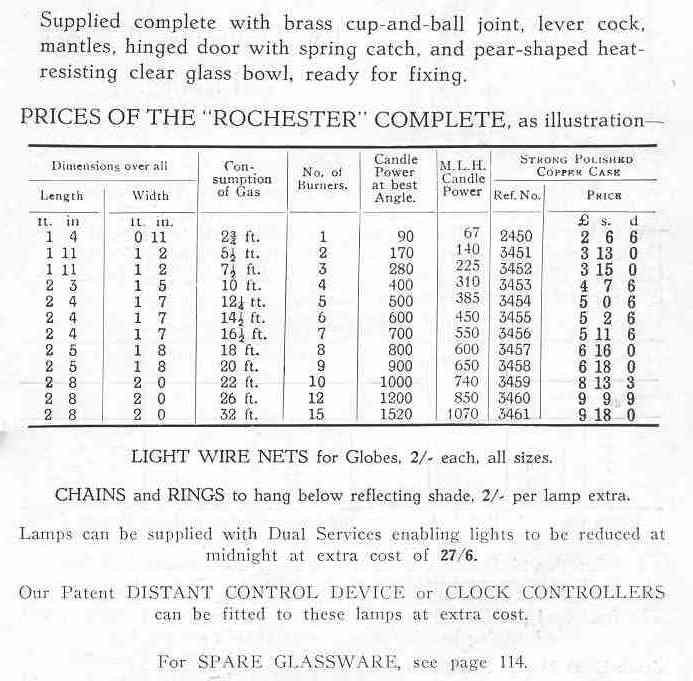
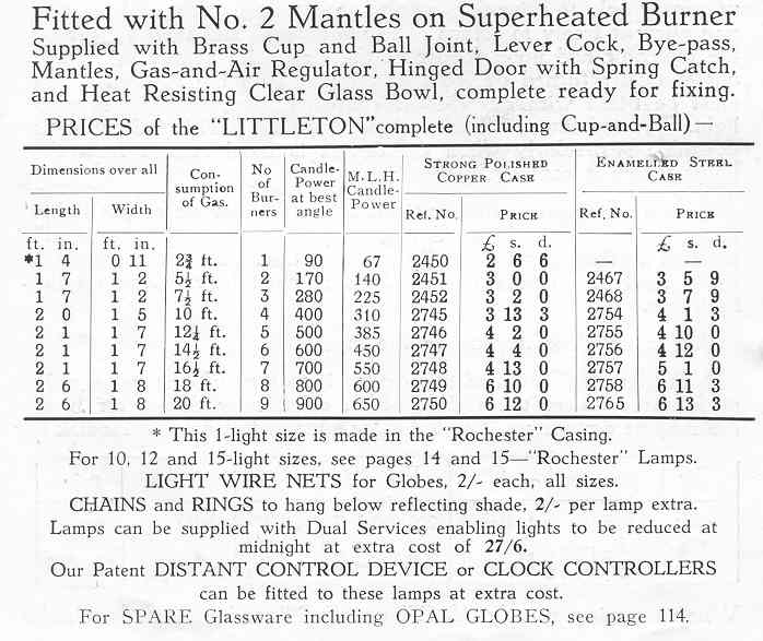
Sizes and prices (in 1937) for the Rochester (above) and Littleton (below)
As you will see from these tables, the largest fixture is the 15 lt Rochester, although the body size for this number of mantles is the same as for both 12 lt and 10 lt. It is worthy of note that the City of Westminster has always used 6lt burners in 12 lt (or 15 lt) casings for their ‘upright’ Rochester’s which can still be seen all over Westminster. I believe this decision was taken in order to increase the scale of the fixture to be more in keeping with the multitude of original and very substantial lamp posts, many of which have been in place since the days of the enormous open flame lanterns discussed under Large Lanterns.
The smallest (1 lt) Littleton is quoted as being ‘made in the “Rochester” casing’. As the charts show that the dimensions, the consumption, the reference number and the price are all identical, I can only assume that it is actually the same item! The Littleton reference numbers all begin with ‘2000’ whereas those for the Rochester begin with ‘3000’. As the 1 lt lamp is in the ‘2000’ series but has a ‘3000’ series shape it can only be a marketing ploy to offer the identical lamp with two different names!
Glassware
As the item most likely to be required by anyone obtaining one of these relatively common lamps, the glassware sizes are of importance. The following chart was made up some years ago from available original details and has now (2018) had further details added where there were a few gaps. Availability of spare glass is not easy depending upon size and quantity. Most common sizes, the 6060, 6061 and the 6062 may be available in borosilicate high temperature glass (like Pyrex). This is of course ideal for gas lamps.(Please enquire.) These sizes are for the ‘pear’ shaped versions. See lecture drawings below showing the two different shapes.
Just one size, the 6062, 5,6 & 7 lt version was made once in a white opal glass for a project using electric lighting to disguise the bulb. A small number of these globes (under a dozen) remain and, because they are not suitable for gas use are available at a reduced price. See also ‘Market Place’.
| Original | No.of Mantles | Flange Dia | Flange Dia | Body Diameter | Body Diameter | Height | Height | Later |
|---|---|---|---|---|---|---|---|---|
| Sugg Ref | or 'lights' (lt.) | Imperial size | Metric equiv | Imperial size | Metric equiv | Imperial size | Metric equiv | Mould Ref |
| 6050 | 1 lt | 5" | 127 | 4.1/2" | 114.3 | 5" | 127 | N/A |
| 6060 | 2 & 3 lt | 7.1/2" | 190.5 | 6.3/4" | 171.45 | 6.5/8" | 168.275 | GLL17 |
| 6061 | 4 lt | 9" | 228.6 | 8" | 203.2 | 8.1/4" | 209.55 | GLL20 |
| 6062 | 5, 6 & 7 lt | 9.3/4" | 247.65 | 8.3/4" | 222.25 | 8.5/8" | 219.075 | GLL12 |
| 6063 | 8 & 9 lt | 10.3/4" | 273.05 | 9.7/8" | 250.825 | 9.1/8" | 231.775 | N/A |
| 6055 | 10, 12 & 15 lt | 13.7/16" | 341.31 | 12.5/8" | 320.675 | 11" | 279.4 | N/A |
The Technology
Principle of operation of mantled lamps
The essential principle of operation of a gas light with mantles is to mix a controlled amount of gas and primary air in exactly the same way as in a Bunsen burner. When a jet of gas issues through a hole (or injector), it expands steadily in a cone shape at about 5 degrees. The dimensions of the airchamber or aeration arrangement are designed to allow the expanding jet of gas to strike the inside of the mixing tube and produce a reduction in pressure at a point opposite the tip of the injector at which position the aeration hole(s) are drilled so that the maximum amount of air can be entrained.
A paragraph of information on the development of the gas mantle will be found in the section Fixtures with Mantles which is part of the Interior Lighting section.
Adjustments for the variety of gases
Traditionally, with manufactured ‘towns gas’ the variations in the gas manufactured in the hundreds of different gas works could be such that to achieve the best performance (greatest efficiency in terms of light per unit of gas) it would be necessary to adjust both the size of the injector and the amount of primary air.
Modern gases such as natural gas and propane are now so standardised that it has become possible to utilise both fixed injectors and fixed aeration. This is by no means the first time that this has been part of the design of gas lamps. Dean Chandler, in his definitive 1936 book “Lighting by Gas” describes the production of gas burners within the South Metropolitan Gas Company and also discusses similar fixed dimension burners going back to 1910. This was of course a significant selling feature within a specific gas company’s area of distribution, illustrating their ability to produce a fixed quality of gas especially in the days when gas was still very largely only a lighting fuel.
Lecture drawing illustrations.
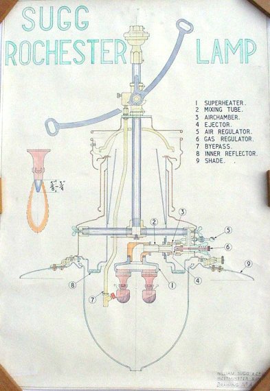
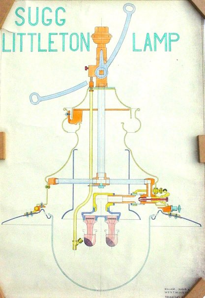
These two lecture drawings showing the cross section of the Rochester & Littleton Lamps illustrate how the similar working parts are mounted in the two different body shapes. The elongated parallel portion of the body of the Rochester shows the additional internal spinnings developed to provide the ‘storm proof’ nature of this model. The working components provided the flexibility to operate on the wide variation in manufactured town’s gas throughout the country and abroad.
The two drawings also illustrate the two shapes of glassware that were offered for these lamps, known as the pear shaped and round globes respectively. The Pear Shaped Globe was advertised as being of “better appearance and gives greater lighting duty than the Round Globe”
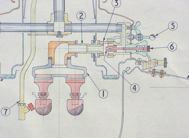
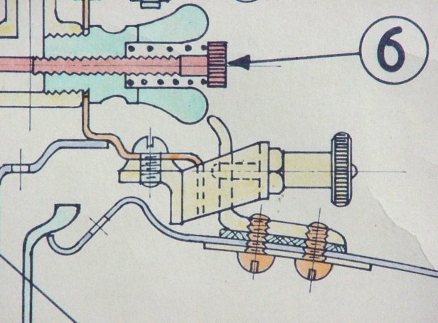
Close up of burner, airchamber and injector of the Rochester
1 Superheater Allows multiple mantles to be mounted together.
2 Mixing tube Where the gas/air is mixed.
3 Airchamber The air is entrained by the flow of gas.
4 Ejector Orifice through which the gas flows.
5 Air regulator Sliding band around the airchamber adjusted by the knob.
6 Gas regulator Needle that can be adjusted from outside to control the gas.
7 By-pass Pilot light for igniting the burner.
The design features illustrated operate as follows:
This Rochester is a suspended model with the gas passing down the vertical tube in the centre of the lamp at the top and then turning right along the horizontal tube towards the small butterfly headed screw where it turns down again arriving just in front of the pale green larger butterfly screw with the red needle numbered 6. The gas then passes through the “ejector”, 4, into the airchamber, 3, where it draws in air through a series of aeration holes which can be opened and closed by a sliding sleeve attached to a small ball ended rod projecting through the casing, here numbered 5. The resultant gas-air mixture passes round the swept elbow into the superheater, 1 and out through the nozzles into the mantles. The pilot, here called by its earlier name of “by-pass”, is shown at 7 with its supply tube coming down the body of the lamp from a take-off immediately above the gas cock, so that it will remain ON when the main supply is turned OFF to the burner.
The quality of design and manufacture is exemplified by little things which provide the user with simplicity of adjustment to give the best performance. The aeration adjuster, 5, slides through a split bush with a collar which squeezes the bush onto the rod to lock it in place so that the aeration setting cannot be lost inadvertently. Likewise, the main injector is fitted with a needle which passes through the butterfly into the back of the jet. A spring fitted under the knurled head ensures that the needle does not rotate and lose its adjustment and thus alter the gas rate once set. All these fittings are made of brass and can usually be relied on to work perfectly for the lifetime of the lamp, however long this might be! (See the later comment on altering the lamp to operate on a fixed injector)
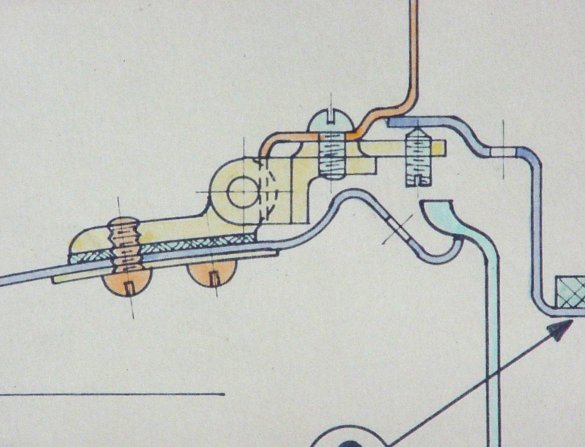
Close up of hinge on the left and spring loaded catch on the right.
Another little detail which is worthy of note, is the spring loaded catch which holds the “shade” in place. This is shown in yellow in the illustration on the right, above. By pulling out the knurled knob against its spring, a peg is retracted from a hole in the catch which is attached to the reflector, allowing it to hinge down for access to the burner and removal or replacement of the glass which simply rests in the central hole of the reflector. The left hand illustration shows the hinge which is opposite the catch and the detail of the small grub screw that is fitted vertically to hold the “inner reflector” against the body. This tiny adjustment screw is a detail possibly made necessary by the method of manufacture of all the body sections which were produced by spinning. This ancient process, whilst capable of producing complicated circular shapes, relies upon the skill of the spinner who forces the material, which starts off as a circular disc or blank, to follow the outline of a rotating chuck machined to the shape required. Because the blank was pushed from one side only onto the chuck, any variation in hardness of the material can produce a slight variation in the size of the spinning and thus the possible need for adjustment if there was an important dimension.
It is interesting to note in both these illustrations the series of small holes that are pierced in both the inner reflector and in the shade. (You can only see these in the drawing as a break in the edge view of the material along with a broken line across the material illustrating the centre line of the hole.) These obviously control the air movement between the underside of the shade and the space that communicates with the inside of the glass globe and thus provides the secondary combustion air.
The air from these holes also passes up into the body in an area outside the burner chimney space where the airchamber is located and thus also provides the primary combustion air. These carefully thought out air paths are what make the Rochester the “storm-proof” lantern compared to the simpler body of the Littleton which you will have seen in the two lecture drawings above. The Littleton has no inner reflector and the gap between the globe and the bottom of the chimney spinning is clearly larger and there is no separation between this space and the body space which holds the airchamber.
The flue path is also very different. The Littleton has a very simple connection between the chimney and the outside air, reminiscent of the simple “cap” on a Windsor lamp, whereas the Rochester has all sorts of extra baffles which appear to be aimed at those plunging and rising winds that are notoriously difficult to control.
The Holyhead Variation
The Holyhead is a wall mounted version of the small Rochester bodied lamp. As you can see the wall mounting is very short so making it suitable for mounting beside doorways or in alleyways. This example and pictures came from Leonard Blacknell in 2013. (CLICK TO ENLARGE)
.
Controls
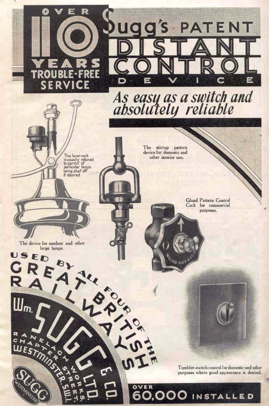
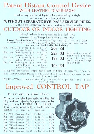
The DCD or “Distant Control Device” is an ingenious method of remotely controlling any number of gas lamps, ‘without separate bye-pass service pipes’. Compared to the CCS or “Central Control System” the DCD requires only one supply of gas. The only limitation would be the overall capacity of the pipework to carry the volume of gas to the lamps being controlled. The largest control tap offered in the literature is, however, 2 inch BSP.
The method of operation is as follows:
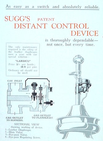
When the control tap is turned to the ON position, gas flows to the DCD valve on each lamp. As the pressure in the pipe rises the diaphragm under the top cover lifts allowing gas to pass through the main passageway to the lamp. At the same time, however, the right hand needle lifts, preventing the flow of gas to the ‘flashlight’ or pilot from increasing to the point at which it ‘lifted off’ and went out.
When the control tap is turned off the pressure drops the diaphragm and the main flow is stopped whilst the pilot resumes its normal flow. The control tap carries a needle operated bye-pass to allow sufficient gas to flow when the tap is closed to maintain the pilots but not sufficient to lift the diaphragm. The DCD carries a pilot gas adjuster which provides a means of setting the pilot gas flow to match the control tap setting.
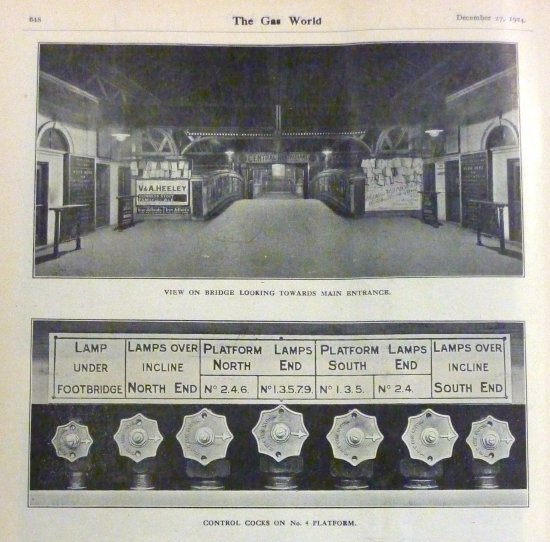
These illustrations in ‘The Gas World’ of December 1924 show the Distant Control taps in use for all the lighting on a major railway station.
Collector’s Corner!
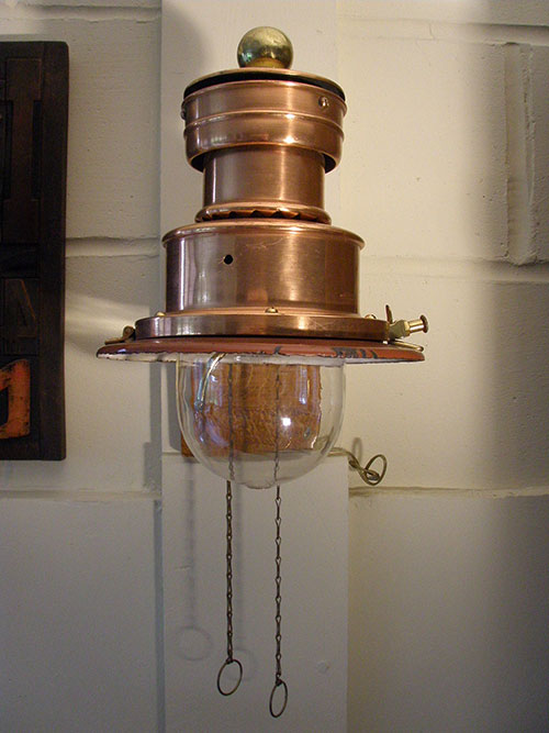
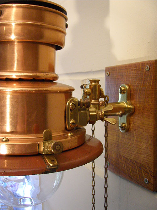
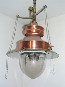
Courtesy of David Sandell
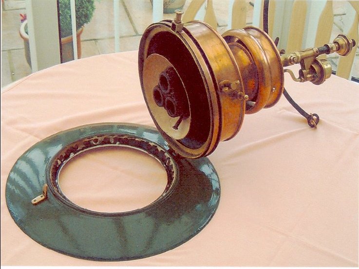
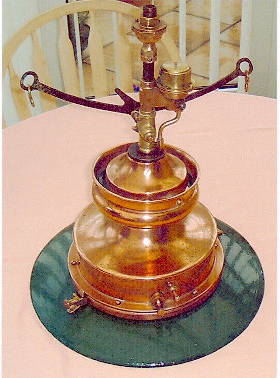
Two views of a very clean 3 lt Littleton lamp complete with its original DCD or “Distant Control Device” as described above. The pictures clearly show the spring loaded catch and the way in which the shade is hinged for access to the inside and also the aperture in the shade through which the flanged globe hangs. The ‘cap and ball’ suspension device is also shown at the top of the supply pipe. This neat arrangement allows the lamp some movement rather than being rigidly attached to the ceiling. Also shown under ‘Collectors‘
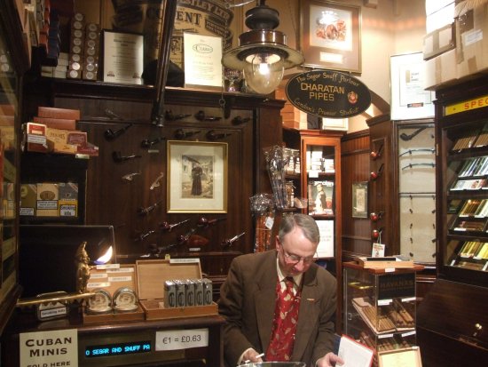
This Littleton still hangs in the specialist Cigar shop in Covent Garden 2007 and is still in use, especially if it gets cold, I am told.
————————————–
This 2 lt Littleton, post mounted on a classic goose neck, is running on propane. With thanks to Phil Ellis in Wales, 2011.
———————————-
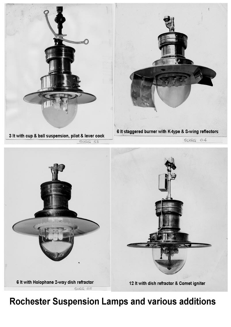
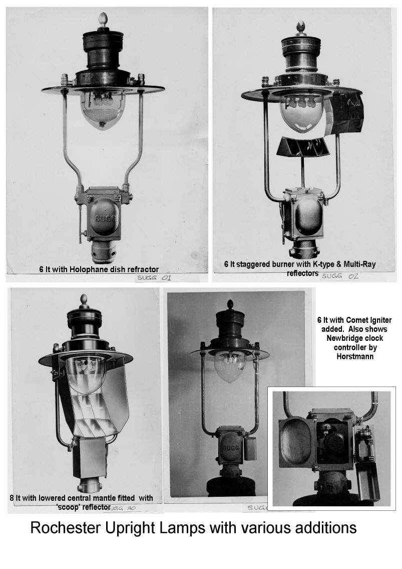
Original Sugg Photographs of Suspension and Upright Rochester’s.
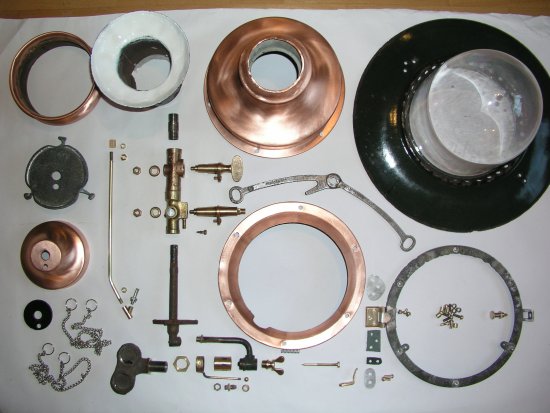
Restoration
The following two pictures illustrate the components of a 2 lt Littleton lovingly restored by Dieter Bruening of Essen. I have included them here as well as under ‘Collectors‘ to avoid them being missed in this section where you may well be looking for this information
STILL UNDER CONSTRUCTION – DO CALL BACK!
Copyright © Chris Sugg 2006-13
Top of page
or
Back to ‘Street Lamps‘
or
Back to ‘Lighting‘
30 responses
Wonderful website very informative. I have a couple of gas lamps, one of which apparently hung at Waterloo station in the 20’s. I recently took to cleaning them from the years of grime that have built up. On polishing the brass coloured shade however I was alarmed to see that I was polishing off the copper colour to reveal a dark green enamel beneath. Am I destroying the original look of the lamp or in some misinformed way restoring it? What was the original colour? Thank you
Can you send me a picture of your lamp? Many railway lamps of the suspended shadowless variety such as the Rochester and Littleton have copper bodies and enamelled (usually green) on the top and white underneath, reflectors. You should not be able to remove the vitreous enamel and of course the copper will polish up bright and shiny. Very few exterior lamps were made with brass as it is a much harder material to form and shape. Chris
I have, I believe, a Littleton lamp that requires a globe. The inside diameter of the flange that holds the globe is a fraction over 7 inches or about 180 mm. I have spoken to Mark at Suggs and it appears that the smallest globe they stock is a couple of millimetres too big. Any ideas? Regards John Crockett.
Hello John, Sorry for delay in replying to your earlier comment but I have since responded to your email. I will be adding a chart to the site showing the sizes of the glassware for the Rochester & Littleton lamps as I realise that the original literature listing the different sizes of the lamps does not show you the size of the glass. I can of course refer to my chart if you tell me the number of mantles on either of these lamps but clearly it would be better for you to be able to find it yourself! Any of these glasses can be made – at a price – from high temperature borosilicate glass (like Pyrex) but it is of course the perfect material for a gas lamp.
Regards, Chris
Thanks for the reply. I think my light is a two mantle Littleton but it has been converted to electric . I have spoken to Mark at Suggs and he measured a diffuser in stock but it appears to be about 2mm too big in diameter. The retaining ring on my lamp has a hole diameter a fraction over 7inches or about 178mm. Unfortunately I don’t have a vernier large enough to measure it exactly so it is a bit risky buying one and finding it doesn’t fit. I really don’t mind what material it is made from or what it costs within reason, the important thing is getting the light back in operation. I am not very good with computers so it was quite by chance I happened across your reply. I had been checking my e mail expecting to find it there. Best regards, John Crockett
My email to you is dated 14th August. The attachment shows the glass for the 2 lt Littleton has a body diameter of 6.3/4″ and a flange diameter of 7.1/2″. It is meant to be a loose fit in the support ring.I also quoted you for the glass in the only material I use which is high temperature borosilicate (like Pyrex) glass. I have repeated the email back to you. Regards, Chris
Hello Chris.Thanks for the reply. Could you give me a price and delivery and method of payment for the above globe as I should like to purchase one as soon as possible. Best regards John.
Hello
I have acquired an upright Rochester lamp and Midland Railway lamp post as used on many railway stations. The lamp is complete in as far as it has been converted to electricity. The only issue I have is that the hinged flanged device for opening the globe has badly corroded and not usable,(I assume it is aluminium?) Do you still hold spares for these lamps, or can you recommend anywhere that I might get one or any alternate fixing? Many thanks
There are several sizes of upright Rochester as you will have seen from the website. They are known by the number of mantles – so that it might be a 4lt or a 6lt or even a 10lt etc. There are no spares as such so usually refurbishers collect several lamps to make up one. (Yes the later models are aluminium – only the early ones are cast brass.) The Upright is easier than suspended versions as the reflector doesn’t hinge, only the ring. It should not be too difficult to form a ring that would support the globe and then devise a fixing for the hinge and the spring button. There may be someone who has what you want in one of the preserved railways but, if you would like to send me a photo of the item you want with the size I could put it on the Market Place section to see if there is any response.
hi, I have a light from around 1900 and was wondering if you could tell me anything about it. we think its a railway platform light. if I could send you a picture somehow.
we would like to restore it. we do have 3 lights all together, 2 have gas connection and one has been attempted to run on electricity.
any help would be great full.
many thanks
paul
Hi Paul, Send your picture as a jpeg attachment to ch***@*******************co.uk If that is a problem let me know and I will send you an address for the real thing!
Hi Chris
Where do I purchase inverted mantels similar to Veritas Alpha M.3773 to fit the Sugg lights at 35 Albert Hall Mansions in 1970?
In addition I am searching for replacement clay radiants for a c1910 fire. They have a 45% angle at the top. The fire is in full working order and has recently passed a safety check.
Thanks!
Hi Catherine,
Most of the mantles used in the UK now are manufactured by Indo International, an Indian company that took on the equipment used by Both Veritas and Auer. The No.2 mantles come in a box of 20 rather than 24 whilst the larger No.3 come in the original 24. They are now very much more expensive – between £6 & £8 each. I carry a small stock and can supply in small quantities plus p & p.
Radiants are more difficult as they vary considerably in size and shape requiring a mould for each one. However, a company called Mantec Technical Ceramics claim to supply a full range although I don’t know about antique ones. Call them on 01782 377550 or enquire at in**@******tc.com
where can i buy an electronic timer with light sensor for my sussex lamp post and windsor gas lamp.
thank you
I think you will find that Sugg Lighting will be able to provide a suitable replacement for what we called an Opto Clock.
Dear Chris,I have just bought on eBay an original what I believe is a 3Ltr Rochester suspended lamp, which used to hang in Long Melford Railway station, I run the Long Melford Heritage Centre so got it back for the village, however the glass shade was broken some time ago, and I need to get a replacement can you help please
Dear John, well done recovering this lamp which is definitely a Rochester as shown in the photo you have forwarded by email. The page on the Rochester & Littleton on this site carries a chart showing the size of the glass for each of the models. As it has already been electrified, judging by the cable I can see, it is unlikely to still have its burner. The listing gives the models in relation to their number of mantles – or lights – (shortened to lt.) This provides the connection between the number of mantles and the size of the lamp and the globe. The alternative is simply to check the diameter of the hole through which the glass will sit and compare that with the chart I added which provides the dimensions and the reference numbers of all the glass bowls. The body diameter must obviously fit through the hole whilst the flange must be larger than the hole so that it does not drop through! Send me your result and I will give you a price for the glass.
Hi Chris,
I’ve just found your website and I’m pleased to learn that glass is still available for sugg lamps. I have two lamps that require the GLL17 glass. If possible I would like these in a standard glass rather than the high temperature glass. Can you give me a quote for cost and postage to Australia.
Thanks Phil
email coming your way!
Brilliant! I’ve owned for over 40 years,as I now know to be a “Rochester”,and have always been impressed by the engineering and level of detail. I had converted mine to,yes,electric and it still looks fine. However,I now need a “pear shaped” glass bowl,from your list it appears I have a 6060 model with approx 170mm aperture, requiring one with 191mm flange. Would you be so kind as to email me a price for supplying and delivering one.I found your website,a fascinating read,and thank you for that. Glenn
Hi Glenn, Thanks for your note. I will send you an email quote for the glass. As a general point for anyone who wants glass bowls for these lamps I have them made in high temperature borosilicate (like Pyrex) so they are perfect for gas but not cheap and I know it is a little over the top for electric but you do get the best and what else do you want for a genuine Sugg lamp?!
Dear Chris,
I have a Littleton Lamp, hung proudly over our dining table. During a recent fire, the glass bowl has been broken. I’m gutted, as was the house, and am now trying to obtain a replacement.
I think the size matches your specs:
6060 2 & 3 lt 7.1/2″ 190.5 6.3/4″ 171.45 6.5/8″ 168.275 GLL17
Is there a chance you can find one for me?
Ever hopeful – thank you in anticipation.
Hello Stephen,
Sorry to hear of your fire. I assume your Littleton was not on gas and thus had nothing to do with the fire? 6060 glassware is very expensive but I have a few very nice polycarbonate globes left over from the main days of producing an electric replica. I will send you an email separately with a quotation. Regards, Chris
I am a volunteer at the Nottingham Industrial Museum and we are restoring a lamp post which was first installed outside the ‘New Museum’ in about 1890. Photographs show it had a large ‘lantern’ , but ours has been converted at sometime to a Rochester style head now with an electric light which appears almost identical to the pictures on your history page.
Can you give me any idea when the Rochester conversion may have been done? The base of the post sustained minor shrapnel damage during a bombing raid during WW2 but whether this was before or after the conversion I can’t say.
Regards
Geoff Buck
This came as an email from another volunteer, Courtney, with different detail and photos so I have replied with other details! Follow up and I will try to add details!
Hi Chris,
I have a Sugg lamp LMS54 which is approx 7 inch in diameter (where the glass bowl would go). However the glass was missing when I bought it. I wandered how I could replace it, I can email you with a photograph of it. Thanks
Hello Georgina,
Email me a picture to the ch***@********************co.uk address and I will see if I can help you.
Hello, I was wondering if you could tell me the thread size that is on the top of the large fitting that screws into the main gas pipe and holds the Main Lever valve on a Suggs lt2 littleton?
Thank you in advance.
Suzannne
Hi Suzanne, There are one or two pieces of barrel that hold the whole lamp together running through the middle and, although there are various different bits and pieces on various models, the size is 3/8″ BSP. That is 3/8″ British Standard Pipe. It was a common size then but not so much nowadays although BSP was such an early and commonly used thread it spread all over the world. The size actually relates to the bore of the pipe which is quite unusual but you can perhaps see why because the user needs to know how much gas can pass through the pipe. In this case the pipe also has a strength requirement of course and ‘barrel’ is even available in different wall thicknesses so has wide uses. Chris
Hello,
I have come across your wonderful site as I am trying to re-create some scale models of the LMS style Littleton lamps as used on Railway platforms (hung under canopies) but I am struggling to find any external sizes or drawings for these items ? I am wanting to 3D draw and print them in O Gauge with an LED as the internal light source. Although from reading your website it would appear the main body is 11 inches, I can find no reference on any website as to the width of the shades ?
Would you be able to help with any of this please? It is to be part of a large model based on Leek station on the old North Staffs Railway.
Regards
Andy