Towards a New Load
In 1960 the Gas Industry was beginning to warm up to the “New Load’ which was presented by Central Heating. In the 15 years since the end of WW2, as the gas lighting load faded fast, Crawford Sugg assisted by his brother, Ray, had developed the Halcyon warm air appliances which were soon copied by other manufacturers and small bore wet systems were beginning to appear. This article, which includes a section on the Halcyon by Crawford Sugg gives a good idea of the state of technology some 50 years ago. The paper that follows the flip book takes it on another 20 years!
[book id=’6′ /]Album 6
Taken from a paper presented to the Institution of Gas Engineers at the 116th Annual General Meeting, London, May 1979 under the title
“Using Gas, Yesterday and Tomorrow”.
by P.Crawford Sugg, Bsc(Eng), A.C.G.I., C.Eng., F.I.Gas.E., F.C.I.B.S
Honorary Secretary, The Institution of Gas Engineers.
Whilst this website is dedicated to providing Sugg specific information, this paper, which was presented by Crawford Sugg in 1979, provided an overview of gas ‘utilisation’ indicating and illustrating the steady improvement in appliance design and manufacture achieved by the British gas appliance and equipment makers “during the last fifty years” (from 1979 back) in all significant aspects of gas utilisation. Thus this paper provides an important chronological history of both appliances and manufacturers peppered liberally of course with the achievements of William Sugg & Co in this context. For anyone interested in the history of the Industry this is an invaluable reference and, with the agreement of the Institution I have been given the opportunity to republish it electronically as a means of disseminating the information more widely and of course filling in details for many aspects of the history of William Sugg & Co which will be found elsewhere within this website. CS.
CONTENTS
1. SUMMARY
2. INTRODUCTION
3. THE MARKET PLACE IN THE EARLY THIRTIES, BACKGROUND 1929 – 1939
4. THE MANUFACTURERS; THE START OF COLLABORATION
7. THE GAS FIRE
10. CENTRAL HEATING AND HOT WATER
12. WATER HEATING
13. PUBLIC AND RAILWAY LIGHTING
14. INDUSTRIAL GAS
15. COKE APPARATUS
16. RADIANT HEATING
17. PROGRESS IN DOMESTIC INSTALLATION PRACTICE
18. INCINERATION
19. TOMORROW? A CRYSTAL BALL (Remember this was written in 1979 C.S.)
20. ACKNOWLEDGEMENTS
1. SUMMARY
After more than a century of original invention and steady improvement in manufacture and design, great progress has been achieved by the British gas appliance and equipment makers during the last fifty years in all significant aspects of gas utilisation. This has now expanded to provide a quarter of the nation’s `Final Uses’ energy with an overall efficiency which is the envy of the industry’s competitors and of inestimable benefit to the economy in the current world fuel situation.
The ‘springboard’ of this accelerating development was the existence in Britain of a body of experienced gas equipment manufacturers, long united within the Society of British Gas Industries, as mature as the supply industry itself and well versed in the application of `methods of test’ and in setting standards of performance for its products.
“Once a Gas man, always a Gas man” is as true of the appliance makers as of the supply industry, but often with a `change of side’ to broaden experience. Recovering from the great social and technological changes of the first World War, and with the spur of competition by the burgeoning electricians, both sides recruited qualified engineers and scientists and their supporting staff. These speedily absorbed the strong traditions of their respective companies, and gained invaluable experience from their predecessors and their own years of service, often lifelong.
A powerful `industrial tool’ was thus forged by the continuously increasing collaboration of the devoted men and women on the staffs of gas undertakings and appliance and equipment makers and from their ranks rose many inspired leaders.
The intense intercommunication of trained minds through the Institution, the SBGI, the BGC, its predecessors and `person to person’, is the true strength of the gas industry and has enabled it to survive in difficult times and to grasp firmly and successfully the great opportunity Nature has now afforded.
Our President has asked the author, who is Chairman of the Institution’s Panel for the History of the Industry, to recount some facets of gas utilisation in the last 50 years and to illustrate these with a presentation of slides.
Because of the wide field to be covered only a broad outline can be included. There must be many omissions which hopefully in due course may be rectified through the Institution’s Historical Records system. Information on the `human’ aspect of the story still requires research.
The paper has been assembled with much help from those, past and present, concerned with Gas Utilisation, and their Companies, the British Gas Corporation and the Gas Press. This generous assistance alone has made a reasonably comprehensive digest possible and the names are recorded, with the Institution’s and the author’s sincere thanks, in an appendix.
Our President has also asked the author to hazard some thoughts as to what may lie in the future for gas utilisation. The author accepts sole responsibility for this part of the paper, although some of his views have been coloured by recent discussions with friends in the industry.
2. INTRODUCTION
In this review I have tried, at the request of our President, to set out some impressions on gas utilisation in the United Kingdom during the last half century. My working life, which in the event has been concerned mainly with the development of street lighting and warm air heating equipment, covered a good part of this period.
I am an engineer who believes that the first essential to making anything new and better is a wide study of the achievements of our predecessors. This may seem obvious, but many of the gas appliances we use today, like the convector gas fire, had a “previous existence”, and their whole concept was for various reasons “in limbo” for many years. Equally, within my own experience, I have seen the same “invention” reappear with succeeding generations of scientists for lack of such study.
The expansion of our industry in recent years has been such that today only a small proportion of those who work in it have direct experience of the patient laying of the foundations of the modern gas appliance industry which took place early in the period I have to consider.
It is right and proper that tradition should be strong in an industry that now approaches its third century of vigorous service to the public. Such tradition requires the passing on of knowledge of the achievements and failures of the past, as well as those of the present, to successive generations of those who serve Gas – a continuing process. The Institution is the obvious custodian of this knowledge and its Library contains many books covering the growth of our industry from its earliest days. I commend the study of these to our members.
I believe that all effort in this direction is worthwhile and to the benefit of the Industry and the consumers of gas.
Here I try within a short compass to outline the more recent use of gas and the main developments in gas appliance design and manufacture. In this I have been helped by many friends in the Society of British Gas Industries and the British Gas Corporation. To do full justice to this subject would require many volumes – which hopefully will one day be forthcoming from writers, each an expert in his specialised “discipline” of utilisation.
Inevitably, because the years of the second war intervened, this story divides into two periods, as does my memory, and it has been convenient to observe this division in the paper.
I found difficulty in arranging the various subjects covered in some logical order, but finally thought it best to deal with them under a series of section headings as shown in the Contents, rather than purely chronologically.
To conclude, and I hope to provoke some discussion, I have risked looking in a “crystal ball” towards the centenary in 2029 of the Institution’s Grant of a Royal Charter.
3. THE MARKET PLACE IN THE EARLY THIRTIES, BACKGROUND 1929-1939
The supply industry, served by about 200 manufacturers, comprised some 1000 separate undertakings of greatly varying size, distributing differing qualities of manufactured gas at various pressures. Sometimes this gas might also carry water vapour and other impurities.
The few major undertakings bore some similarity to the later Area Boards, with substantial resources in trained manpower and extensive laboratories. They were of. high reputation, influence and authority within their boundaries and their “character” was largely determined by the great men who controlled them and whose names are recorded in the Annals of the Institution. Many of these contributed greatly to the development of gas manufacturing processes.
A large number of medium sized gas undertakings, many municipally owned, comprised the greater part of the remainder, a few of which had considerable technical resources in utilisation. Many other undertakings, some very small, operated by an Engineer or Manager with a few experienced staff, including sometimes his own family, completed the British market. These undertakings had much practical experience of utilisation but no laboratories other than for testing the gas made. It must be said that very occasionally it would scarcely burn.
Most of the undertakings also sold coke, often directly to the public in bags from the Yard; some few also delivered coke over their area. Thus the industry provided a dual fuel service to the public and industry. Other by-products of carbonisation helped to keep the price of gas competitive, in the range 6d-9d per therm (2.50p-3.75p/th), the cheaper gas being in the North, near the coal pits.
Abroad, British owned or controlled gas companies were to be found in all parts of the world, often with offices in London through which they purchased their equipment. In London also were the Ministries and the Railways, then recently grouped, with their regional headquarters about the country. There was still a tenuous commercial connection with the main European Gas Authorities, left over from the previous century.
A gas appliance market differing more from that existing today would be hard to imagine. According to their resources, and many firms were small by today’s standards, the various manufacturers attempted to cover this market by copious advertising in the Trade Journals, by “travellers” and by visits of their principals to the larger undertakings.
Inevitably, with travelling much less convenient and road travel much slower, manufacturers in some lines had acquired “parishes”, often around their own location, in which their sales effort was more concentrated and correspondingly rewarded.
Similarly, individual large undertakings would on occasion dictate their own special requirements for appliances and particular manufacturers designing to suit would benefit by long-standing collaboration, often over many years.
On receiving an order the first duty of an appliance maker was to study the records of calorific value and specific gravity of the gas for the undertaking concerned. Differences in coal quality around the country resulted in quite substantial differences in the characteristics of the gas supplied in different places (including the smell and the toxicity). These differences increased with the introduction of vertical retorts and water gas. Most gas appliances accordingly had adjustable injectors and aeration controls and often an inlet pressure adjusting screw, as governors were usually optional extras. The bunsen burner was nearly universal, and some burner noise was accepted as normal.
4. THE MANUFACTURERS IN THE EARLY THIRTIES; THE START OF COLLABORATION
This market situation tested the ingenuity of the appliance manufacturers to the. limit. Without exception, all had instilled in them a sense of the responsibility for safety in gas utilisation which rested on them, but otherwise they were free to initiate new designs and improvements as they wished, and as often as they liked. The “traveller” would then offer them to various customers who would then display them to the public in the gas showrooms which dotted the country.
Inevitably the manufacturers gradually began to specialise in the field of utilisation in which they were more successful or best known and this process accelerated as development and manufacturing facilities improved for that field of effort, and costs and prices reduced.
The process of amalgamation of appliance makers, to be expected in these circumstances, had already started, notably with the origin of the Radiation group in 1919. Such groups invested in more extensive development laboratories manned by qualified staff.
Soon after, the large undertakings enlarged their own utilisation laboratories, notably at Watson House and at the Central laboratories of the South Metropolitan Gas Company. The concept of approved appliances based on British Standards was initiated, and with the continuing interchange of information between buyer and “maker” the pattern for the expansion of the modern gas appliance industry was set.
The result of this collaboration was nationally significant, judged by the performance of any industry. Many thousands of new appliances were developed and marketed which made an important contribution to the improved standard of living of the country. A revolution was made possible in the equipment of the new houses which were erected in the building boom after the first world war, after the long era of cheap coal drew to a close. Nowhere was this more in the forefront of public interest than in the kitchen, where the duties of the housewife were rendered much less laborious and time consuming by the new appliances. Equally significant changes occurred in all other fields of gas utilisation.
In what follows I have endeavoured to describe the major changes which occurred in this story of development in the applications of gas on which I had or could acquire information. I have instanced, as it appeared to me, equipment demonstrating these points of change and illustrated these where suitable pictures were obtainable. Other equipment, no less important to the general evolution of the discipline, will be shown in the presentation, but for some earlier examples little trace seems to remain.
I am only too aware that I may have made some errors of omission, in dates, or attribution. As Chairman of the Institution’s Panel for the History of the Industry, I would welcome any correction or additions to the various chapters which members may be in a position to contribute. A note to the Panel will be much appreciated to improve the accuracy of its records in the sphere of utilisation.
5. THE GAS COOKER
1929-1939
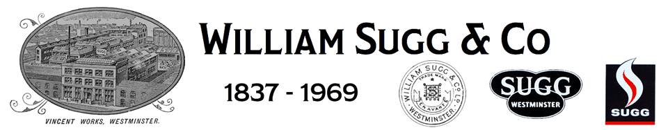
The use of gas for cooking dating from about 1837 (Sharp), both in the home and for catering, had become almost universal by 1929, and long established manufacturers provided a wide range of equipment, much of it of the heavy cast construction with some enamelled finish inherited from the foundry practice from which many of these firms originated. The cookers were simple, devoid of automatic ignition or controls other than in some cases an optional oven thermostat (the Regulo) which had been introduced by Wright in 1923 in association with the bottom flue lagged oven. They weighed 2.1/2 to 3 cwt and were expected (along with many products of British industry of the time) to “last a lifetime”, without repair. What little service was required, such as greasing the taps, was provided on demand by the local gas fitter, for the “quid pro quo” of a cup of tea. Some parts, including the burners, could be lifted off and put in the sink with hot water and washing soda when the housewife thought a “clean up” was desirable. Many individual consumers seemed content with the old black iron cookers, particularly in catering; these had already been in use twenty or more years and were almost indistinguishable from cookers of the last century. The makers’ effort was therefore to develop new equipment and instil in the minds of the public a completely new image of what a gas cooker should be.
With the beginning of electrical competition in the cooker market this process started quickly and fructified a few years before the hiatus of World War II with the general change to construction based on enamelled steel pressings, bottom flue outlets to the oven, and greatly improved “streamlined” appearance and ease of cleaning. One or two cookers had flash tube ignition for the hot plate from a permanent pilot, but the oven thermostat remained the only generally adopted “automatic” and its use had become fully integrated into the housewife’s cookery books and her daily life. The chefs in hotels still preferred manual burner control of the visible flame and many still do!
Salient dates in this progress were the introduction by Main in 1926 of cookers with most surfaces enamelled and a choice of colours, and by Sugg in 1932 of the enamelled “Berkeley” cooker with non-aerated oven burner. The Radiation New World Range was popular by 1933 and those had “Regulo” oven thermostats as standard equipment. The marketing of the GLC 0 Cooker as a replacement for the old black hire cookers took place in 1934. This and the larger GLC 1 design were the first cookers made in very large numbers on assembly lines. (Main and later Parkinson). They had constant pressure governors, fixed gas air controls and an oven thermostat.
Parkinson introduced the hinged hotplate cover about this time and the fashion for a straight sided cooker with shut down lid carrying a folding plate rack spread to most makers in the next few years. The Parkinson “Renown”, originally a “one off” model for the house presented to King George V at the time of his Silver Jubilee, was marketed with automatic hotplate ignition by flashtube in 1937.
A variation of this form of ignition, by push button controlled pilot, was adopted by Radiation in the same year. The successful effects of these developments in gas cooker design may be judged by the fact that the orders were placed in quantities of 25 or 50 thousand at a time. Main alone made 210,000 GLC 0 and 1 cookers in 1937.
Throughout this pre-war period many gas companies continued to offer black cookers on hire at a few shillings a quarter and renovated them by degreasing and repainting before they were supplied to yet another consumer, so that the “old fashioned” image of the industry was still propagated to an extent. Nevertheless much progress had been made in efficiency and in outward appearance and it was possible to buy a cooker with many convenient features in blue or green enamelled finish to suit the decorative styles for kitchens then popular. Thus the situation remained up to the outbreak of the second world war.
The Cooker, Post War.
The first need after the war was for cookers for new housing and modifications of pre-war designs were made, including in 1947 revised versions of the GLC 0 and 1. The Main 177, the first example of a built-in cooker, was used in the prefabricated housing. This had spillage collection devices.
The Radiation 1430 series was introduced in 1947; this and its successors were a complete departure in construction, being built up from sheet steel pressings attached to an angle iron frame, with spring door seal.
These and other constructional features became generally adopted over the next few years and much attention was devoted to improved appearance. General Gas Appliances led with the “Raymond” cooker, designed by Loewy in 1951, which was entirely finished in white enamel and had many features then new to the gas cooker; the grill under the hotplate was in a separate “box”.
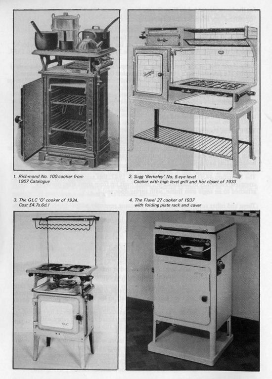
The “London” cooker, successor to the GLC 0 and 1 cookers, was produced in 1951 by Main, entirely with steel pressings, for the NTGB, and incorporated many of the new features at a low price. In 1953 the Cannon “A125” with high level folding grille set a new style which was followed by other makers, notably Parkinson in the “Renown V” which had automatic ignition to all burners.
Some luxury cookers by Radiation were of double width with a plate warming compartment beside the oven and a griddle plate in the hotplate.
Changes in pan supports to give improved pan stability were followed by various makers, and in 1957 General Gas Appliances marketed the Auto range with automatic time control and flame safety valve for the oven.
The Radiation “Rangette” appeared in 1958, much wider and with a warming oven to one side and a central grill. In the next two years automatic hot plate ignition, usually by a flash tube and pilot, became standard practice on all cookers by agreement between the Gas Council and the SBGI and special cookers for disabled or blind users were designed and made available on National Health prescription.
In 1960 the Cannon A133 with rotisserie under the grille and the Flavel split level built-in “Space Master” were introduced, while General Gas Appliances marketed the “Leisure 60”, again in conjunction with the makers of kitchen fitments.
Further detail improvements occurred in the next few years, notably in the application of timing devices, in grille and door design, but by 1966 the need was to produce conversion sets for natural gas, and most other development work had to stop until 1970.
In that year self-cleaning oven linings were introduced by Stoves Ltd and rapidly adopted by other makers.
Spark ignition to hot plate burners followed in 1971 on the “Leisure 5-Star” cooker and much attention was devoted to the simmering adjustment of hotplate taps, more critical with Natural Gas, and the use of the flame safety valve on oven burners became mandatory.
In the last few years there has been some departure from the almost universal white finish and some most attractive coloured cookers are to be seen to match decorative schemes for kitchens, some of which have been influenced by continental styles. The increasing adoption of built-in ovens, with separate hotplates is also apparent.
The great deal of attention devoted by so many to the development of the gas cooker over these 50 years has resulted in a range of British equipment second to none in the world, fully able to compete in the market place against allcomers and successfully achieving this aim.
6. CATERING EQUIPMENT 1929-1979
Gas-heated equipment has long been the commercial caterer’s first choice because of its speed, flexibility and high thermal efficiency in comparison with the use of any other fuel. E.W.B. Dunning of Watson House considered that in 1957 gas served over 90% of the catering establishments in this country.
Throughout the last fifty years a number of manufacturers have specialised in this field, some exclusively, and a full range of equipment has been offered which has shown a progressive development from the early black cast iron construction of the major items to the vitreous enamelled or stainless steel favoured today.
Design for hygiene and ease of cleaning by the avoidance of crevices and ledges has greatly improved the appearance, but the need for mechanical strength to withstand the heavy treatment the equipment may receive will always remain. Much improvement has also been effected in such fittings as thermostats and thermometers, in avoiding explosion hazard and recently, in the interests of fuel economy, arrangements for reducing automatically the tendency to leave burners alight when not in use have been introduced. New types of appliance, notably for counter equipment have been developed.
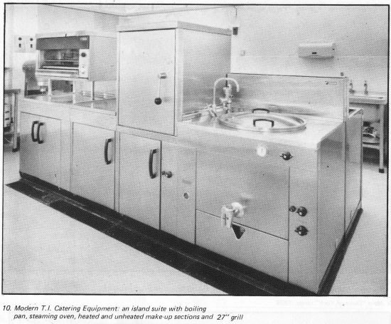
The catering industry has itself expanded rapidly in the last 3 decades with changes in the social structure of the nation. Full sequence automatic control equipment, pilots and electric ignition systems, oven timers, forced convection fans and other sophisticated devices have been incorporated as appropriate in modern gas catering – equipment to permit safe and correct operation by recruited staff with less experience than the traditional chef.
A full description of the very wide range of gas catering equipment must remain outside the scope of this review; the appliances now available, made since 1954 to British Standard 2512 and Approval tested by Watson House, can truly be described as masterpieces of gas technology. Although basically stemming in concept from the gas cooker, much expertise derived from industrial and other spheres of gas utilisation has been incorporated within the apparently simple and pristine exteriors that they present to the user and often to the public.
7. THE GAS FIRE
The Gas Fire in the Thirties
Gas was relatively a very expensive fuel for heating throughout the thirties but its convenience compared with the almost universally used living room grate, and the incorporation by architects of fireplaces with 9″ x 9″ chimneys in all the main rooms and bedrooms of all types of new (and existing) buildings had resulted in a market for gas fires, and an extensive range of such fires was to be seen in every gas showroom.
These gas fires were mostly of cast iron construction and had aerated burners, sometimes with a duplex tap to give choice of all columnar radiants heated, or only the central 2 or 3. The output was nearly all radiant heat obtained with an appliance efficiency of about 40%, but this effect was obtained rapidly from cold and they were a much more convenient source of heat for those who could afford to operate them than the solid fuel appliances then available, even though these could easily be lit with a gas poker. Many households retained a coal or coke fire for the main living room and employed gas or electric radiant fires in all other rooms for intermittent use.
To follow the chain of events leading to the modern gas fire it is necessary to go back to the beginning of the century when the then current gas fires had the reputation of producing a stuffy atmosphere. This was due to occasional spillage of products of combustion (which were slightly sulphurous) and the overheating in convector types of room air containing dust in tubular or similar heat exchangers having a low volume flow.
Much science based development work to solve this problem followed the introduction of the single columnar radiant in 1907 and the “Leeds” method of measuring radiant heat in 1909.
The “Lancet” test of 1914 for detecting spillage of products was carried out with no extension flue on the fires (as it remained until after the second world war), so that very little thermal lift was available within the appliance to prevent the spillage under the laboratory test conditions. When installed in a fireplace with the normal 9″ x 9″ flue the flue pull not only removed the products completely but induced an air change on the room comparable to that due to a solid fuel fire, which was then evidently regarded as the paragon of comfort.
Thus in 1929 and for many years thereafter “the popularity of gas fires was attributed to the provision of reasonable ventilation equivalent to that of a coal fire”. Any convected heat produced by the fire was soon lost up the flue; only the radiant heat was of use and the choice of fire size was determined largely by the number of people expected to sit round the fireplace.
That the designers of these gas fires did not seek to provide appreciable convected heat, although the convector gas fire had originated in the 1880s, may perhaps be ascribed to the high natural air change of much of the housing stock, with many chimneys and suspended floors, and also to the solid uninsulated walls and roof spaces with correspondingly high heat loss.
A virtue was made of this high flue air change by the Gas Industry as ensuring “healthy ventilation”. In retrospect the case was overstated through necessity. “Comfort” expectations were admittedly much below those we now enjoy and clothing generally heavier, so that the radiant gas fire was accepted by a public used to an open coal fire, attained a high standard of design and appearance and met the public need in the years before and during the War.
Compared with earlier fires, the typical gas fire of 1929 had lighter columnar radiants with solid backs and open fronts, improved back bricks, and burners with venturi mixing tubes, multi-hole injectors and eddy filters giving quiet well-aerated flames. Adjustable aeration and pressure adjustment screws were provided in the absence of a governor against possible supply pressures of 3″ w.g. to 10″ w.g. Taps with quiet turn down had been evolved. Such features greatly increased the acceptance of the gas fire by the public, not least the reduction in burner noise.
It seems probable that the first signs of departure from the then current concept of a gas fire as a purely radiant heat source and a return to the convector principle was reported by A. Forshaw, Chief Chemist of R & A Main. He reduced radiation and increased convection output “to improve the rapidity with which a room could be heated”. The “Rayvector” fire of 1926/27 incorporated an air passage behind the fireback and was “sealed” to the fireplace with a closure plate.
At the time this idea does not appear to have affected the main stream of gas fire development, possibly because there were then no significant numbers of houses with cavity wall construction and reduced heat loss and natural air change. Radiant efficiency continued to rise, governors became standard fittings, and the new more attractive “Portcullis” type block radiant was evolved around 1935, with better control of secondary air and consequent higher temperature within the radiant. This gave the radiant fire a “new image”.
However in 1938 the “CR” fire (General Gas Appliances Ltd) was designed specifically on the convector/radiant concept with an overall efficiency notably greater than the then existing fires. It was claimed for this that “one therm was saved in five” and that “on a two part gas tariff at 4d per therm (1.7p/th) the running cost was equal to that of a coal fire after five hours operation”. Here lay the real future for the gas fire, but the war intervened.
The Gas Fire, Post War
The aerated burner gas fires induced dust and required frequent maintenance. To eliminate this, neat flame burners were developed in conjunction with new radiants and very low burner noise level finally achieved.
The post war fuel price rises and the building of houses and flats designed with perhaps only one fireplace in the principal room and electric sockets elsewhere directed attention afresh to the insulation and draught proofing of dwellings and the efficiency of heating appliances. Moreover, the adoption of the neat flame burner, for very good practical reasons, had reduced the radiant output by some 25%.
There was therefore an urgent need for “convection devices” to restore and if possible improve the overall efficiency of the gas fire.
The need to regulate the flow of air through the fire to the flue to that necessary only to prevent spillage was recognised; ventilation could be controlled by openings separate from the flue way. The “Lancet” test was made much more realistic to take some account of the effect of flue pull on an installed appliance by specifying the attachment of a flue extension of 2′ height for the performance of the test for spillage of products. A degree of thermal “lift” within the fires thus became available to draw the hot products leaving the radiant through a heat exchanger to provide a warm air output and improve overall efficiency.
Of greater importance, the revised “Lancet” test, associated with suitable design, permitted clearance of all products of combustion with a greatly reduced flow of air from the room and through the appliance into the flue. These products were accordingly less diluted and at a higher temperature when they entered a heat exchanger. Moreover the convected warm air from the fire was then able to circulate throughout the room instead of being lost up the chimney; the gas fire could become a true “space heater”.
An early post-war application of these principles was the elaborate “Port Royal” fire (Bratt Colbran). This had a flue break and was stated to be “33% more efficient” and to give full heat service for a living room or lounge.
The Cannon “Gas Miser”, retaining enamelled cast construction in contrast to other gas fires, was another distinctive version which became popular from 1954 onwards.
The Bratt Colbran “Flamborough” of 1957 used a passage behind the radiants to heat the convected air and this was followed by the “Kingsbury” which had a sheet metal heat exchanger above and behind the radiant section.
It became apparent that by increasing the proportion of convected output and reducing the radiant heat, the overall efficiency of the unit could be raised without detriment to the comfort it provided or the need for unacceptable height and cost. The flue gases from the radiants entered the heat-exchanger at a higher temperature, increasing heat transfer to the convected air.
The Main 271 of 1959 was an early example of this concept and probably the first high efficiency (approx.65%) gas convector fire.
One further problem remained – the now substantial flow of convected air stained the wall above the appliance. This was solved by discharging the warm air forwards through a slot so that it was separated from the wall above by air at room temperature induced from the sides of the fire. The “Queen” fire (Sugg) initiated this feature and also the use of aluminium-coated steel pressings as suitable material for its two heat exchangers with vertical convection air passages in front, between and behind.
Appliance efficiency was now around 65% and the operating cost and performance on suitable tariffs was notably acceptable to the consumers for continuous room heating. It remained for Flavel to innovate the wooden cased style with the “Debonair” fire of 1961 and with it to initiate the wide range of high efficiency radiant/convector gas fires integrated with the furnishings of the modern living room.
In the search for still higher efficiency the Radiation “Crystalglow” fire (1962), with a panel of heat resisting glass rods in front of the radiants gave still better control of secondary air.
The very considerable task of providing conversion sets for natural gas for all the current designs of gas fire and many of the earlier models still extant on the district then followed, involving a return to the aerated burner or jet and the solving of associated problems of noise and linting. Redesign to take full advantage of the new gas was the next step.
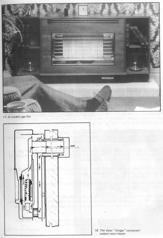
The availability of one-piece ceramic panels with which the radiant opening could be completely sealed made practicable the balanced flue gas fire (Valor in UK) so that the limitation imposed by the need for a chimney on the use of this type of appliance has been finally removed. This heater has an overall efficiency of 67.5%, 20% of which is in radiant form.
In this brief description many “offshoots” in the line of engineering development have been omitted, but one must merit inclusion. The early “Metro” Log Fire of 1932 had a most attractive appearance. In two sizes, with gas rates of 50 and 100 cu ft/h (500cV) these were equivalent only to normal fires of 5 and 10 radiants. The concept of adding a “fire effect” to a convector/radiant gas fire of high efficiency appeared with the Robinson-Willey “Sahara” of 1963 and has become a popular feature, although it involves an electrical connection.
Very recently Main have introduced the “Richmond”, a true “log” fire with flickering flames, but by controlling the secondary air completely with a glass panel and using a heat exchanger above they have retained full overall efficiency and provided a fresh meaning to the term “fire effect”.
Needless to say, in line with other domestic gas appliances, the modern gas fires are fully provided with convenient means of ignition and control. They represent a major achievement on the part of the Industry and enjoy a high degree of public esteem.
So many extraneous factors have affected the long story of this appliance that I feel that it has been necessary to mention the impact of some of them on its development.

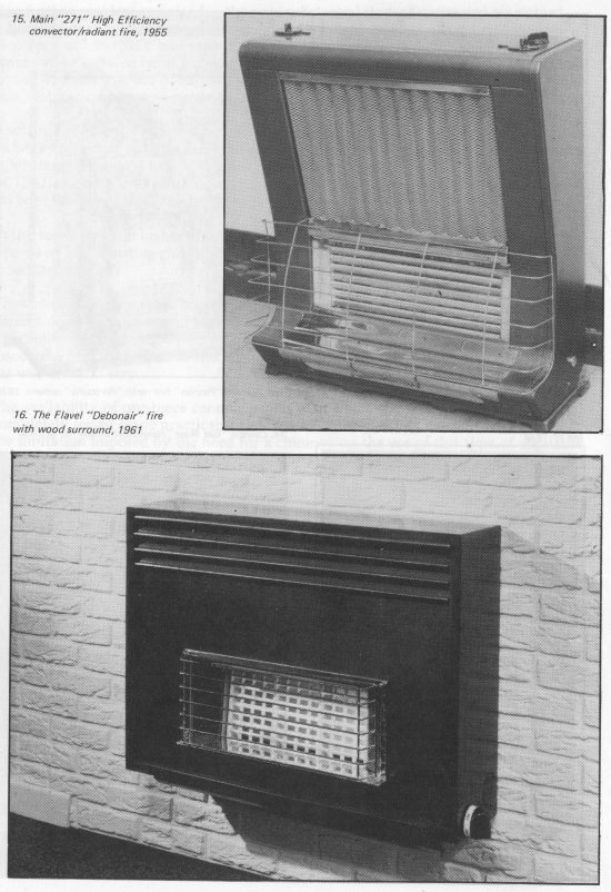
(Fig 15 Main 271 date below should read 1959)
8. REFRIGERATION 1929-1979
The “flame that freezes”, a perennial subject of public curiosity, has been of great value to our industry as an “anchor” in the kitchen for the gas cooker.
In 1921, without knowledge of previous work, two students at Stockholm University, who were seeking a suitable pump for their experiments on absorption refrigeration, accidentally left a bunsen burner alight near by. They found the evaporator covered in frost next day. After further development their invention was acquired and improved by AB Lux, later Electrolux.
In 1926 the first Swedish made unit was marketed in Britain. This had a wooden cabinet insulated with cork and lined inside with painted sheet metal, and was water cooled so that it had associated tanks and a hand pump, or else involved paying a small water rate. The capacity was 10 cu ft, and the price £48.10s.0d.
The Food Preservation Act, forbidding the use of many chemical preservatives, was also introduced in 1926, but for some years refrigeration was regarded in Britain as a rich man’s luxury – the initial sales were made by reference to Debrett and travelling the great country houses!
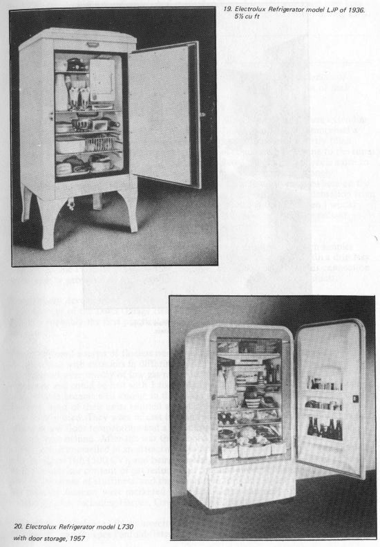
Manufacture of the water-cooled unit started in Britain in 1927 and continued, but with a steel cabinet, until 1930, when air-cooling was introduced – greatly simplifying installation. The “idea” of refrigeration in the kitchen remained hard to sell.
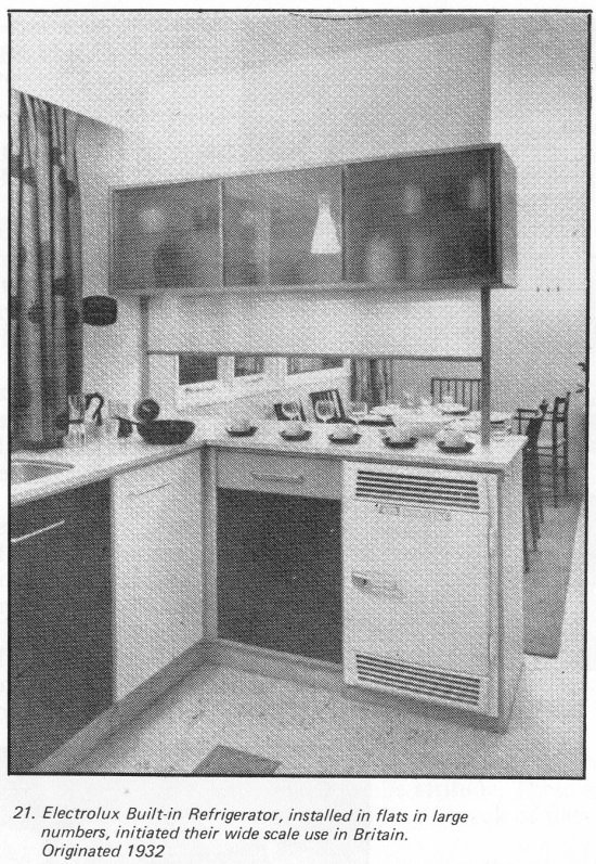
In 1932 the “building-in” to the kitchens of large blocks of flats of smaller units, down to 1 cu ft capacity, began to change the public attitude. These small units cost only £19.10s.0d. As many as 550 were built into a single block of flats.
The Gas Companies played an important part in promoting the sales of the gas operated models, laying the foundations for wide scale domestic use with a range of sizes, and the UK factory had to be extended.
In April 1936 the manufacture of electric absorption refrigerators was discontinued in the UK and all effort concentrated on gas models.
The original patents expired after the war and some other manufacturers later produced gas operated refrigerators.
In the late 40s and early 50s the government sponsored pre-fabricated homes produced in hundreds of thousands were each fitted with a built-in refrigerator. Ever since, a refrigerator of one sort or another has become standard equipment in the British kitchen.
Steady improvement in design has provided larger low-temperature storage, door storage and larger cubic capacity in more compact cabinets.
By 1972 the original manufacturer had made 4 million domestic units and now very large numbers are also made for caravans, with the “flame that freezes” burning LPG.
9. CONVECTION HEATING
I have grouped under this heading the variety of flued and flueless appliances of varying degrees of complexity and differing application which emit most of their output by convection.
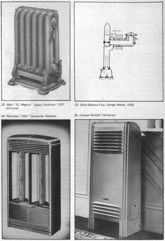
The “steam radiator” was an early example which had a long period of use extending well into the twenties. The appliance, made by Richmond and others, comprised a cast iron double loop radiator mounted above a burner chamber and partly filled with water. The steam circulated in the radiator and condensed, returning to the sump below to be re-evaporated. The steam pressure operated an adjustable needle valve to control the gas flow. The very critical nature of this adjustment was strongly emphasised in the literature and hopefully there was a safety valve somewhere on the appliance. There was no flue, but a tray on the base plate collected condensation from the combustion chamber, which opened at the front for lighting. The aim I would guess was to achieve as high a proportion as possible of low temperature radiant output in buildings such as schools and churches and in hallways.
In 1927 the Davis “Steamless” Column Radiator was introduced, a much simpler concept where the flue gases circulated inside a radiator-like casting; again a drip tray was fitted. The Parkinson “Indusa” of 1931 was arranged with a fresh air connection to outside to provide a measure of ventilation induced by the rising products.
A significant development in 1935 with far reaching consequences was the Balanced Flue concept of the Davis Garage Heater, made entirely of cast iron, with luted joints; this was probably the first practical room-sealed appliance. I refer to this later in Section 17.
There followed a series of flueless non-condensing convectors of the simplest construction with exteriors in differing styles and finishes. These had neat flame burners and were mostly of low gas rate. The Cannon “Beacon” Radiator was columnar and could be had with 1 to 3 columns, with the further option of a boiling ring. Flavels became well known in this field in the middle thirties and the flat crackle finished front of their units emitted appreciable radiant heat and the appliances were very widely used. They were of cast iron and sheet steel construction and with legs to ensure a low floor temperature and a reflecting insulated back to reduce the wall temperature behind. After the war the Cannon “R7” Radiator, of cast iron construction enamelled in an attractive colour became popular. It had a gas consumption of 20 cu ft/h (500 CV), and being flueless could not be used in normal rooms. With the sulphur content of gas reducing all the time these appliances did not produce any undue sense of stuffiness, and similar units in differing styles, mostly burning less gas than the Cannon, were marketed in the late forties and early fifties by several manufacturers, including Harper, Cowper Penfold, Radiation and Parkinson.
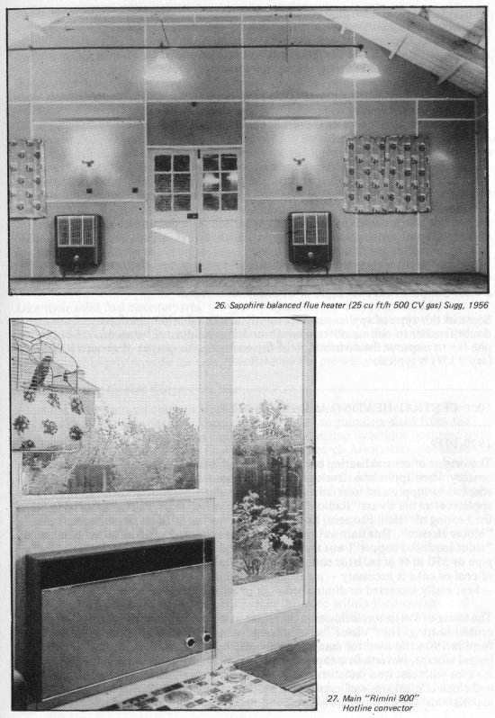
Interest in the balanced flue convector returned in the early fifties and the Radiation “Balancia” and Cowper Penfold (later Sugg) “Sapphire”, which was developed at the Central Laboratories, became prominent and some very large installations were made, such as the NAAFI depot at Claygate, where Sapphires were fitted in hundreds of Nissen Huts. The Sapphire was originally available with inputs of 10 cu ft and 20 cu ft of gas (500 CV) and the efficiency was high, in the order of 75%. Other sizes were eventually made and restyled casings designed.
The Cannon “JR7” with input of 6000 Btu/h appeared in 1957 and some units were made with a small gas fire in the front, vented through the sides. These were probably the last of this simple type as the whole concept of flueless equipment fell into disfavour.
I hesitate to group the most ingenious and sophisticated series of appliances known as “Hot line” in the same heading as those mentioned above. I believe the Wilkins & Mitchell “Servisaire” of 1968 was the first of these having forced convection and combustion and a very small balanced flue, with every modern control concept necessary to ensure safe and convenient operation. The output is 12,500 Btu/h, entirely as warm air, and the efficiency very high.
The Baxi “Brazilia” Convector heater also had two fans, and there were others with differing arrangements. The Parkinson “Rapide” had pre-mixed gas and air supply to a most compact heat-exchanger of extruded aluminium.
Some of this type of appliance are currently marketed in simpler form and are no doubt familiar to our members. Recent models use a normal balanced flue but retain one fan to improve the distribution of the warm air. An output of about 10,000 Btu/h (say 3 kW) is typical.
10. CENTRAL HEATING AND HOT WATER
1929-1939
The origins of central heating by hot water can be traced back before the turn of the century when appliances developed in the previous decade for storage water heating adapted to supply cast iron radiators or heating pipes by gravity circulation. Such appliances as the Ewart “Radion” Circulating Gas Boiler were listed as suitable for the heating of “Hall, Passages, Rooms, Conservatories, Offices, Greenhouses” and “Motor Houses”. This unit was often externally mounted and had waterchambers of “stout hardened copper”, was tested to 50lb/sq inch and could heat 750 ft of 2 in pipe or 350 sq ft of radiator surface. The main sales points made were “No storage of coal or coke is necessary – no attendant required – no dust, dirt, smoke or smell – heat easily increased or diminished – lit or extinguished as desired”.
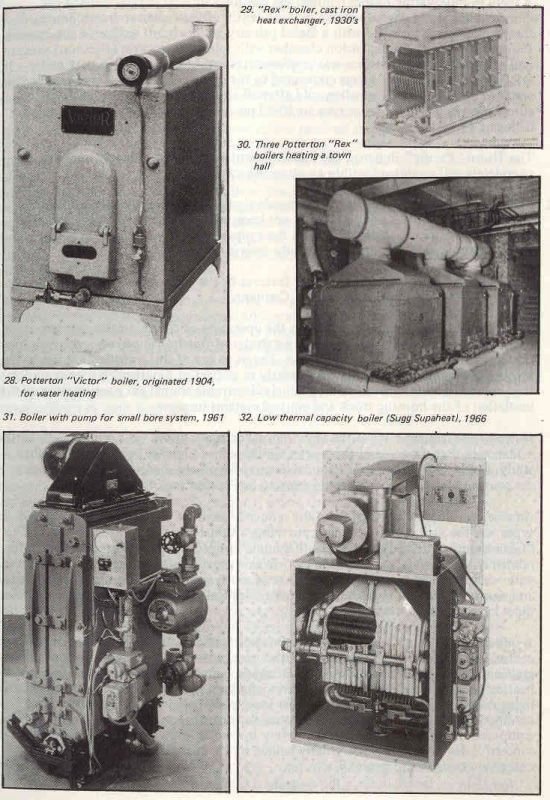
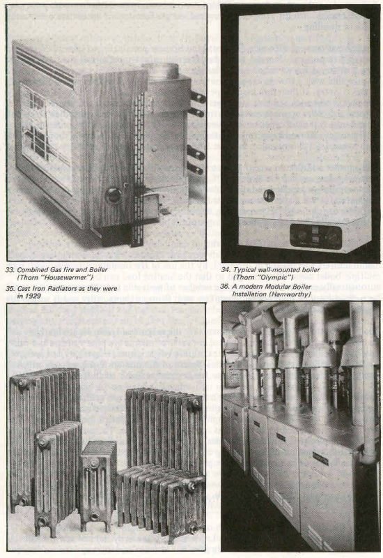
The name of Potterton is however that most associated with the pioneer days of gas central heating. The “Victor” series of cast iron boilers was introduced in practical form in 1904 and used for many years thereafter mainly for hot water supply by lagged storage. Nevertheless the technique of using gravity circulation central heating systems with cast iron radiators and modulating water or air temperature thermostats and clock control was well established by this company by 1929. The number of installations was then relatively small and for domestic use confined to “luxury” dwellings owing to the disparity in fuel costs compared with solid fuel boilers for which coal could be bought at about £l per ton. With steady development a range of such boilers became available during the thirties from those supplying domestic hot water only for flats up to units of 1.1/4 million Btu/hr.
Installation in batteries was practised where still greater output was required and extensive gas fired boiler rooms were equipped for many large buildings.
These boilers were of sectional cast iron construction with provision for cleaning waterways and flueways by removing front covers. Straight single or multiple luminous flame “silent” burners superseded the earlier aerated burners about 1935. Ignition was by pilot flame with a “maintenance” gas rate when the thermostat was satisfied. Larger boilers were lit in two stages to warm the flues. Control and ignition systems to provide bi-metal flame safety protection and automatic control through relay valves were available as options by 1938. The boilers could be flued into existing brick chimneys without undue risk of condensation, the efficiency being of the order of 70%. Where possible they were installed in a basement to assist the water circulation to remote radiators on the ground floor. “Cut out” valves, limiting circulation to the upper part of the storage cylinder and “night valves” to prevent circulation when the boiler was off were provided to save gas.
Like their solid fuel counterparts, the gravity systems, sometimes assisted by circulating pumps, with their high thermal mass and cast iron radiators were most suitable for continuous or nearly continuous operation. Within this limitation on flexibility, they were nevertheless durable and reliable and found numerous applications, largely outside the domestic field, in the pre-war years.
Central Heating by Hot Water, Post War
After the war improved controls were fitted to the pre-war boilers, including thermoelectric flame safety devices and thermostats resistant to gum deposited from the gas. Apart from this no significant change in central heating technique occurred until 1957 when Brooks of the British Coal Utilisation Research Association published full details of his work on pumped small bore pipe systems for radiator circuits. For a number of commercial reasons this concept was publicised widely by the oil fuel interests but in the event redounded mostly to the benefit of the gas-industry whose equipment was less costly and better tried and whose ability to provide installation contractors and service was already well founded. The price of oil was then appreciably less than that of gas, but the advantages of the latter set out so clearly by Ewart sixty years earlier were such that they outweighed the price difference in the minds of a public intent on achieving a higher standard of living with labour saving equipment.
A new generation of boilers, some with pumps included within their casings, and pressed steel radiators, soon appeared to take advantage of the small bore system, which could readily be included in existing houses of all kinds. Initially the boilers were for use with conventional flues and the technique of lining existing chimneys to obviate possible condensation troubles was rapidly developed and became universal. By 1961 room sealed boilers with balanced flue terminals had been marketed and thousands of domestic installations had been completed. These in general relied on control of the temperature of the circulating water rather than on air temperature thermostats, individual radiator valves being adjusted as necessary. The boilers also provided domestic hot water supply by gravity circulation to an indirect storage cylinder with calorifier.
Other manufacturers developed ingenious new equipment for the market- which was strongly supported by a supply industry becoming less worried by prospective peak loads, and much work was carried out by Watson House on the properties and design of domestic heating systems. Many new installation contractors entered the now rapidly expanding field to implement the orders received mostly through the gas showrooms. Notable among the new departures in boiler construction in the early sixties was the “Servowarm” concept of a “master radiator”, in effect a long narrow balanced flue boiler similar in external appearance to and serving as a radiator for the room in which it was installed. Apart from this appliance most boilers retained cast iron as the material for the heat exchanger, with vertical water ways finned or with projections cast on to improve heat transfer. Multi-functional controls with thermoelectric flame safety protection and associated water temperature thermostats provided “on-off” operation and became widely adopted as the result initially of the enterprise of Honeywell.
The regular maintenance recommended by the gas boards and the manufacturers for this relatively sophisticated gas/electric equipment involved the training and equipping of many skilled personnel. No consumer is prepared to wait when he is completely dependent on a heating system which has failed. The successful provision of rapid service became a major necessity to the success of gas central heating, and was duly organised by the industry to match the expansion in the numbers of installations and variety of appliances. Watson House provided courses of two weeks duration for the senior officers in each Region involved in the subject.
The next phase of boiler design was the introduction of the low thermal capacity heat exchanger. One form of this had been used in instantaneous water heaters and circulators for many years, with copper construction to resist the corrosive effects of sulphur in the gas. The “Ascot 604” central heating boiler of this general type was marketed in the fifties only in N. America, where the natural gas was relatively sulphur free.
A fresh application of the principle was made in the middle sixties using aluminium to resist corrosion and provide good heat transfer. Hentsch of Sugg developed the light weight “Supaheat” boiler with pump forced water circulation and fan forced circulation of the combustion air and products to and from a balanced flue terminal only some 6″ square. The compact heat exchanger consisted of 5 lengths of “Integron” finned tube arranged in two layers above an aerated burner. The deep aluminium fins bonded to a smooth bore copper tube provided a high rate of heat transfer to the water. The forced balanced flue made the unit virtually independent of wind conditions and the terminal could be mounted on any exterior wall accessible within 3 or 4 feet of the back or either side of the boiler without regard to the proximity of projections or other features of the wall face. This control of air supply and flue flow also made it possible to increase the efficiency without other penalty to over 80%.
Because the heat exchanger contained only a pint of water the unit was truly a “low thermal capacity boiler”, and on lighting it reached full output almost immediately.
A form of modulating burner control was included and the temperature of the domestic hot water was adjustable independently of the radiator circuit. Some of these boilers were installed with a sealed primary water circuit similar to the simpler European systems. An expansion chamber with rubber diaphragm (Flexcon) pressurised on one side with nitrogen was employed instead of an expansion tank and a safety valve and pressure gauge connected to the circuit. The system is charged with Water to a pressure of 7 psi when cold after all air has been vented through an automatic valve. The pressure rises to 30-40 psi during operation, the safety valve lifting at 43 psi.
The Thorn “Pacific” Boiler of the middle seventies used this principle and was completely self-contained within an attractive case.
The pressurised system apparently demands above average installers to achieve the necessary degree of soundness and has not been widely adopted here. It avoids the need for feed and expansion tanks and their pipework and will no doubt play a significant role in the future, as it already does in Europe.
Other boilers having somewhat similar features to the “Supaheat” were marketed by, amongst others, the pioneer Potterton Company.
The effects of low thermal capacity on the operation of central heating systems has become the subject of much comparative study by Watson House, vis-a-vis the more traditional forms of boiler construction. The outcome of this investigation has so far favoured the lightweight boiler, particularly in respect of practical efficiency under the part load conditions which increasingly determine annual gas consumption as the insulation of the housing stock and control systems improve.
However the protagonists of the high thermal capacity boiler have replied with further evidence in their favour and the matter would seem to remain open to still further study. Horizontal finned tube heat exchangers have been made in cast iron, so that the two competing concepts would seem to be “coalescing” to some extent.
Another development arising from the reduced weight of heat exchangers of both types was the wall mounted boiler, providing a valuable saving in kitchen space. The “Glowwarm” and the recent Thorn “Olympic” boilers are examples of boilers with relatively light cast iron heat exchangers in this group. Flue arrangements associated with wall mounting have been the subject of much ingenious design, both balanced and conventional flue types being available. Vertical balanced flues using concentric pipes have also been devised.
A quite distinct concept which has proved most valuable in the expansion of the central heating load became possible with improvements in automatic control and ignition. This is typified by the Baxi “Bermuda” introduced in 1966 with the central heating boiler concealed behind a convector/radiant gas fire, the whole installed in the living room fireplace. This saves valuable space elsewhere in the house and with a readily removable gas fire gives good access for maintenance of the boiler. Such equipment must necessarily operate at very low noise level, the subject of much successful development work, greatly helped by the installation at Watson House of extensive acoustic equipment.
A range of combined appliances of this type has become available from the principle manufacturers with differing convector/radiant gas fires to suit decorative needs and types of dwelling.
A combination appliance of a different kind became practicable to take advantage of the rapid response to demand of the low thermal capacity boiler and the high rate of heat transfer of finned tube heat exchangers. A good domestic hot water supply can be provided with a storage capacity notably less than the 30 gallons commonly used in this country. It therefore became possible to make the boiler and lagged storage cylinder in one enclosed unit, no larger than a normal floor mounted boiler. The control and other connections could then be made in the factory, including those to a finned tube calorifier capable of transmitting the whole output of the boiler to the stored water and readily accommodated within the tank. The “Impala” boiler of 1971 is an example of this practice; another is the very recent Robinson Willey “RW2000”.
Still another addition in recent years to the extensive range of boilers available for central heating are the Chaffoteaux “Corvec” boilers of French manufacture based on European design practice and descended from the type of lightweight heat exchanger originated for the instantaneous water heater. These are normally wall hung for domestic use and have balanced flues, and are employed commercially in multiple conventionally flued assemblies for larger outputs.
With the changeover to natural gas firing in many large buildings, central heating systems of very great output have been required. This need has been met, largely by manufacturers specialising in this field, by the use of the modular principle, with such multiple boiler assemblies arranged so that the heating load can be accurately and automatically matched by varying the number of boilers in use. This equipment has been the subject of much development by such firms as Hamworthy and is within the commercial gas sphere.
The contribution of design improvements by the makers of controls, circulating pumps, heat emitters, radiators, fanned convectors, microbore pipe systems and other essential ancillaries to the successful expansion of gas central heating by hot water has been equally important to the development of the market. Equipment of much improved performance and appearance has become available in all these categories.
This brief and necessarily incomplete outline of progress in gas central heating by hot water has attempted to describe a major industrial effort, which since the trauma of conversion in the sixties, has taken rapid advantage of the design and marketing opportunities afforded by the copious supply of natural gas. The provision of central heating equipment in millions of homes and many other buildings has notably improved the standard of living of the country and has increased the domestic gas load by a factor of at least seven since pre-war days.
11. WARM AIR CENTRAL HEATING
To vary the style of this review, much of which is necessarily like a catalogue, I propose first to recount an outline as I now see it of the early days of warm air in Britain. This work started immediately after the last war and my experiences may be typical of those of SBGI colleagues concerned with new product development in the unsettled conditions which prevailed for some years.
Ignorant of each other’s activities, both Dr Davidson of Radiation and I and my brother Raymond began independent investigations. I believe Dr Davidson initially obtained an American Chimney furnace and installed it with an extensive balanced duct system in a specially built test house. He later used water/air systems and then direct heat transfer to the air.
At Sugg, we made a design study of possible water to air systems, which would also have provided domestic hot water, decided they were then too expensive and settled on the simpler principle of one stage of heat exchange between flame and room air. After abortive attempts at forced product circulation and making small centrifugal fans which proved too noisy, a small multi-tubular heat exchanger was developed with an output of 12,000 Btu/h. This was designed without welded joints so that there was complete freedom in all senses for expansion and contraction of the parts subject to heat from the burner. A draught diverter with 3″ back flue connection was incorporated, together with bimetal pilot safety device and overheat trip and temperature sensitive fan control. A 2-blade shrouded axial fan, 6″ diameter, hung below on rubber mountings, driven by a shaded pole motor of 9W output of BTH manufacture. All the parts other than the motor had to be designed and made, no suitable components being then available in Britain.
The efficiency proved to be 75% between one third and full on gas rate; the electricity consumption was 1 unit per day.
I have given some detail of this original unit because it remained deliberately unaltered for many years, except for the type and power of the fan and the adoption of chrome diffused steel for the heat exchanger tubes. It served a variety of air heating purposes at a final output of 17,000 Btu/h (flued) and survived conversion; many of this early design are still in use today.
Mounted in a rectangular casing with louvred front and air intakes at the sides, the unit first became a free standing fanned convector heater, the “Halcyon” model H of 1948-9. Limited numbers were tested in shops, waiting rooms, offices and the halls of houses, including my own, to determine user reaction, durability of the heat exchanger and liability to dust accumulation within. There was also the all important question of the reaction of the Gas Companies to a domestic gas appliance dependent on electricity supply. No difficulty ever arose in this latter respect.
By arrangement with Croydon Gas Company, who donated the installation and test meter, several of these `H’ type heaters, including one double unit, were fitted by R. E. Johnstone (then Industrial Engineer) in a church hall, the scene of great dust raising activity by Boy Scouts by reason of the wood worm in its structure. Much testing of temperature gradients, etc. was performed and it became apparent that user satisfaction was uniformly high. Most of all the then few users were impressed by the rapidity and even distribution of the heating effect and the economy of operation. The noise level also proved acceptable.
Quantifying the test results showed that the circulation of the warm air by a fan improved the temperature gradient to the extent that the desired breathing zone conditions could be obtained with 10% less heat input than with natural convection. The heat loss through the ceiling and upper side walls was evidently reduced by the lower air temperature to which these parts of the structure were subject. A steady demand built up for the type H and a flueless type HX which was introduced, and we invested in a moulded bakelite fan. In 1952, with much improved outer casing, the model J was marketed. A model K retained a cheaper casing with square corners.
Meanwhile, a trial installation was fitted in my house of 2500 ft super, using the same heat exchanger but with ducts leading to the hall and lounge and a “diverter” to give choice of warm air flow to either space. A magnetic valve and lounge room thermostat were added.
Despite the output of only 12,000 Btu/h, the effect in providing quick comfort all over the 18’x 12′ lounge was striking and a neighbour immediately requested a similar installation.
This was the genesis of “Halcyon Preferential Heating” later re-christened by D.R. Wills “Selective Heating”. The output of the heater was linked, with some margin, not to the heat requirement of the whole house, but to that required to rapidly and fully warm the room in which the occupants relaxed. By moving the diverter the warm air could be directed into the hall to provide background heating there and in any bedrooms of which the doors were open.
Much later, when gas central heating improved, this seemed a strange concept, but in the early 1950s gas was regarded as a very expensive fuel, to the point where the continuance of the industry was in doubt in many minds and housing estates were being planned without any gas mains. It became evident that “Selective” heating also linked the operation of a heating appliance with nearly twice the efficiency of current gas fires and of very low thermal capacity closely to the living pattern of the occupants to provide much improved comfort for the consumption of little fuel and no labour – particularly was this the case when the heating demand was intermittent.
About 1952 I uprated the air heater in my house to 16,000 Btu/h output and at the suggestion of D.R. Wills reverted to the use of a centrifugal fan. This was belt driven at 400 rpm to reduce noise by the same type of 9W output motor, and was more suitable for use with ducts. With a test meter installed the equipment was then operated for a further three years and the durability of all parts established. The opinion was confirmed that the capital and operating costs of the ducted “Halcyon” were each much less than for the existing heating systems, but there was then little demand for domestic equipment fired by gas. The construction of three more power stations had been authorised in 1950 and the first of many blocks of flats with electric underfloor heating had been erected at Kirkcaldy in that year.
The country then ran short of electricity generating capacity with the greatly increased demand for this form of energy (some 14% per annum) and 100% Purchase Tax was imposed on all domestic equipment connected to the supply mains. After long negotiations with Customs and Excise I succeeded in removing the tax completely subject to mounting the Halcyon 6′ high in commercial and industrial premises only. All the existing models were rendered unsaleable “at a stroke”.
With functional outer casing, still around the same heat exchanger but with a 4 bladed 9.1/2″ diameter 20W output fan to throw the air down to floor level, the Halcyon more than survived this sudden metamorphosis. As Model L (later W) in single and multiple units it proved acceptable in a variety of non-domestic applications following extensive tests by SEGB & NTGB in the Eastern Division, the latter at the instigation of Mr S.G. Aberdein, the Commercial Manager.
In some cases 10″ x 10″ ducts were used with concealed installation and a variety of duct components to suit was listed in 1954, together with models arranged to provide fresh air intake for ventilation. A very wide variety of duties were performed, including LCC hutted schools, large public houses, workshops, offices, warehouses, golf clubs, multiple stores and shops. To facilitate this, model M with top draught diverter and flue outlet was added and the output increased to 17,000 Btu/h per unit.
Much experience in dealing with heating problems was acquired by Sugg staff mostly familiar with the use of gas for street lighting. Enthusiasm was generated by the new outlet for their considerable capabilities. Those Gas Board personnel who knew of the heater were equally keen. Much encouragement and help was received from Watson House and the Central Laboratories of the South Eastern Gas Board, and from Anderson at Bradford and others.
The change to chromium diffusion of the heat exchanger tubes was then made as soon as this process became available. This eliminated the need for annual cleaning inside the untreated mild steel tubes hitherto used, which in the event lasted about 12 years, but were by design easy to replace at a cost of £2 per set. It is notable that of the four million chromium diffused steel tubes eventually used in the original Halcyon heat exchangers I am not aware of a single failure by corrosion.
The purchase tax situation then eased somewhat and the original domestic heating application was brought to its first fruition in 1955, although to reduce this tax the motor and magnetic valve were supplied separately for site fixing. The fan control of the earlier heaters was omitted completely and the leads of the motor and magnetic valve were fitted with plugs and sockets so that a gas fitter could if necessary replace them. No means of service then existed for electrical components on domestic gas equipment.
This unit became the original F45 Halcyon heater. The heat exchanger had already survived 8 years use in various forms and the fan bearings and seals after 300 m revolutions were declared by SKF to have an indefinitely long life under their conditions of use. The motor already had a sophisticated lubricating oil circulation system. I thought the unit could safely be tried on the market and some more test houses were sought. This was the disadvantage. I had always associated the use of the domestic Halcyon with the construction of new houses. Fortunately I did not have long to wait.
Mr Tony Bishop, a director of an SBGI Company, had heard of the Halcyon and installed two and a circulator in a new house designed for the purpose which was erected for him at Wimbledon. Another important lesson was learnt here. The three appliances were originally each flued into a very well ventilated attic, a common practice then. However condensation occurred on the cold water tank and dripped through the ceiling. The flues were extended and fitted with sheet aluminium ‘fish tails’ each side of the ridge board of the roof, the ridge tiles lifted about 2″ and wire mesh fitted to exclude birds. Thereafter flues terminating in attics were abandoned and the idea developed into the ridge terminal since so widely used.
More individual houses were built with the F45 Halcyon and selective duct sets, and through Guy Fuidge of the South Eastern Central Laboratories and J.R. Blackwell of the New Housing Office of the Board contact was made with the builders Wates Ltd of Norbury, and a test installation was fitted in the 150 year old home of Mr Neil Wates in Chester Row, London. I remember that E.S. Harris of NTGB HQ Division completed this operation from survey to test run in 3 days, and that Neil Wates later toured the country delivering addresses on the advantages of warm air heating.
In August 1956 Norman Wates, the chairman, inspected the test equipment in my home (at 3 hours notice) with his colleagues Bland and Roy Pitt and others. The prototype Wates open plan “Dormy house” was then erected in a few weeks at Sutton and I fitted the F45 “Halcyon” and selective duct set into the lower part of the airing cupboard. South Eastern Central Laboratories then furnished and instrumented the house, and with some difficulty, because it was the time of the Suez crisis and petrol was rationed, simulated occupation for most of the winter of 195657 and distributed a very comprehensive illustrated report nationally to the Gas Boards.
Provided with a pass key and the freedom of the Dormy House by Wates, I demonstrated the system during that winter to my own colleagues and subsequently to builders and local authority representatives who visited the house from many parts of the country. I always started the demonstration with the house “stone cold”, and put the visitors in the small dining room while I poured out some coffee; by the time I served it they were remarking on the warmth.
Before the Dormy House tests were complete Wates altered their standard 3-storey flat and maisonette block to take the “Halcyon”, and also an incinerator and a warm air heated drying cupboard. The first of these were erected in Ardmay Gardens, Surbiton in 1957 and at this stage time-switch control was added and became usual practice thereafter. Many hundreds of dwellings of this design were subsequently erected.
Wates redesigned other dwellings for the “Halcyon”, followed six months later by New Ideal Homes, with all their two storey house range. This was the `end of the beginning’ for the widespread use of gas warm air in quantity-produced private sector housing.
Then followed several steps which consolidated this new application of gas. These included the handling of the inquiries directly through the Gas Boards for say 10%, and installation by them for as little as £11 each – one Halcyon represented several times the then average domestic load. Mr V. Stanton, Commercial Manager of the South Eastern Board, introduced a special tariff and negotiated the complete removal of purchase tax on the grounds that the Halcyon and its ducts constituted a “central system”. This was done between midnight, when I was asked by E. Wulstan Atkins for a complete illustrated history of the system, and midday the following day.
I had accepted that there was at that time only limited capacity for designing domestic duct systems on strict principles. The Instruction literature was therefore confined to the use of one size of duct (later 12″ x 6″ was added), with length limits to the living room, another limit for other rooms and a limit on the size of house. Any architect or builder could envisage a practicable system for a new building design with this and other drawings and guidance given in the Data Sheets. He could also obtain detailed plans from the Sugg drawing office on request.
Thus was set a pattern which resulted in the rapid development of gas warm air heating in a period when much new housing construction was under way. Collaboration with architects “before they put pencil to paper” was practised by both Gas Boards and appliance manufacturer with benefit to all.
During 1958 Sugg developed the room-sealed 22,000 Btu/h F.S.D. downflow “Halcyon” (later called the F60) originally for the Se-duct flue system. This selective heater and its successors, adaptable also to conventional and balanced flue, became by far the most popular type of “Halcyon” heater. The inclusion of the water circulator in the air heater in the F45WH and F60WH models followed.
Many other makers entered the field, some early and some late, with varying degrees of success. Predominantly used in new housing, the low cost selective heating system secured many new consumers at a critical time for domestic gas utilisation. As one builder said to J.R. Blackwell “Lunch is on me: for the first time in twenty years you have got something I want.”
In 1959 Potterton introduced a water-to-air heat exchanger and fan unit for use with their boilers. This had four spigots to which 4″ diameter flexible or rigid ducts could be attached to distribute warm air to registers or ceiling diffusers, the latter for use with low level return grilles. With a boiler of 44,000 Btu/h output, whole house heating could be provided by warm air distribution to registers sited below windows. The High-Vee system of 1962 was on the same principle.
More powerful gas to air appliances also became available from several makers. A Halcyon of 45,000 Btu/h output, with provision for fitting a Radiation C28 Circulator within its casing, and considerable fan power, was in production in 1962. This was often used with “perimeter” duct systems with floor grilles directing air vertically to blanket windows with excellent results.
While whole-house warm air systems were installed in increasing numbers of new private houses and flats, the selective system remained the usual choice for the public sector: both forms of duct system were later used in existing dwellings, notably by Cameron Heating or for rehabilitation schemes.
In the year ending 3lst March 1965 some 50,000 gas fired warm air units were installed, 60% more than in the previous year and virtually all in new construction where the architect had complete freedom of choice of the system adopted. A good proportion of these buildings were local authority tower blocks, with room-sealed heaters and water heaters, and sometimes drying cupboards, connected to Se-duct flue systems. Underfloor electric heating, previously so popular because of its low capital cost, had finally proved too expensive for tenants to operate.
For the next four years this progress kept pace with the acceleration of new building; more than 100,000 warm air systems were fitted in 1969. At one time Sugg alone was heating 25% of all new construction. I have heard that in all forty manufacturers entered the field, a number very much reduced in recent years as the demand for equipment for new buildings fell.
The Safety record of the selective warm air installations was carefully watched by the authorities and proved to be exceedingly good. All the appliances other than the original F45 Halcyon had thermo-electric flame safety protection with the Perl device or magnetic valve or the Honeywell or similar manifold gas control unit. The supply industry carried out a major operation to modify all the former type of magnetic valve, when quite suddenly instances of failure to close were reported. Investigation by Watson House and SBGI showed this to be due to a minute deposit on the pole piece; the latter was isolated from the gas stream by incorporating a diaphragm, a practice then made standard. Most of these malfunctions occurred on air heaters, but some were on boilers.
Another improvement was the adoption of ducted return air on all warm air heaters having conventional flue systems. This followed the introduction of some larger foreign models with greatly increased fan power; with these the depression in a heater compartment could much exceed the 0.005″ wg which I had used as a limit in the earlier Halcyon installations, where the available flue pull was usually 0.015″ wg.
A further change in installation practice was confined to multi-storey buildings where “means of escape” provisions were required by the fire authorities, who became concerned that smoke or toxic gas might pass through warm air duct systems if a fire occurred in a dwelling.
This concern, although unsupported by statistics or by any single instance of such an event, became the subject of a major investigation at the Fire Research Station, funded by the Gas Council and the Electricity Supply Industry. The latter had now also adopted warm air distribution with its “Electricaire” heat storage system. A special two-storey house was built under cover at Boreham Wood, very fully instrumented and equipped with a heater and whole house duct system. Some thirty differing tests of half hour duration were carried out over many months in which substantial and repeatable fires were lit in the living room. Observers from many authorities were present – I represented SBGI. Although the test fires produced highly toxic dense smoke from burning plastic foam, nothing visible entered the bedrooms and the concentration of toxic gases there and in the kitchen proved to be well below the safe limit. However, the living room door warped away from its frame from the heat of the fire and the hall became smoke logged. I took the precaution of recording the degree of door warp for each test and each new door. I remember we stared for some time at the numerous results of the smoke density tests taken in the hall with a sense of complete mystification. Doodling, I plotted smoke density against door warp and obtained a straight line through the origin — the smoke in the hall was apparently entirely due to the gap at the top of the door, nothing had been transmitted through the duct system. In fact the tests confirmed that all low level openings transmit air into a room in which there is a fire.
A code of practice embodying the use of low level return ducts (the supply ducts were already at low level), with a maximum living room thermostat setting of 80°F and maintenance of the integrity of the “escape route”, was agreed with the Fire Research Station, for eventual incorporation in the Building Regulations applicable to dwellings to which “means of escape” requirements apply. There was no change in practice on two-storey houses, nor was any retrospective action thought necessary on the multi-storey blocks. This episode in the warm air story is closely associated with the devoted efforts of R.D. Bruce, lately Services Manager of Watson House.
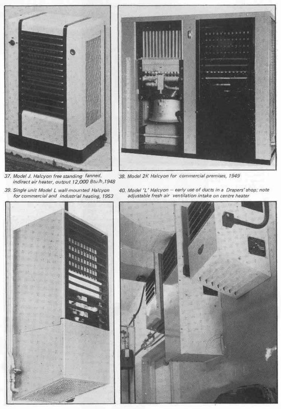
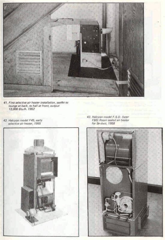
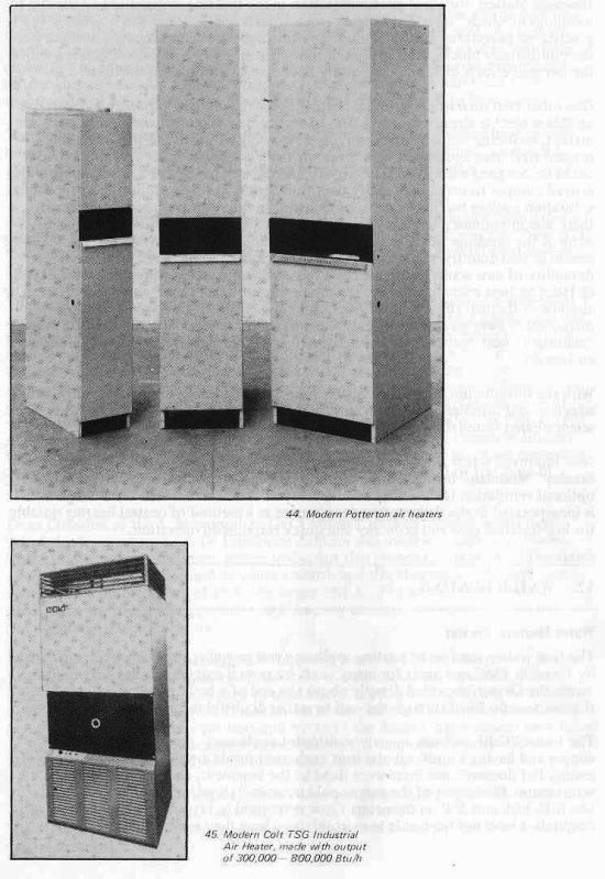
One other step forward in warm air heating needs recounting, although my narrative on this subject is already overlong. The advent of new manufacturers in the warm air market, including some of American origin, introduced the use of the “clamshell” pressed steel heat exchanger. With these, air heaters incorporating a water circulator could be designed with a width of only 1′ and depth of 2′. These heat exchangers also proved cheaper to make in quantity than the original Halcyon multitubular type, but a duration cycling test had soon to be included in the Approval procedure because there was sometimes a tendency for fatigue cracks to develop by thermal stress in parts of the pressings. A Canadian Gas Association test previously devised for the same reason in that country was adopted by Watson House and has since ensured the durability of new warm air appliances. I felt some satisfaction when the original type of Halcyon heat exchanger passed the severe duration test twice without ill-effect. The absence of thermal stress in this design probably explains why so many of early manufacture have given some twenty years of useful service. Nevertheless, the cheaper “clamshell” heat exchanger is now universally used for quantity produced domestic air heaters.
With the introduction of a Warm Air Manual compiled jointly by BGC and SBGI the selection and installation of warm air heaters and ducts is now placed on a firm science-based foundation available to all concerned.
New improved warm air equipment, incorporating in the case of the Johnson and Stanley “Modulair” heater refined operational control by electronic devices and optional ventilation features has been developed since conversion to natural gas. This is incorporated in the design of modern houses as a method of central heating notable for low installed cost and economy and quick response in operation.
12. WATER HEATING
Water Heaters, Pre-war
The first widely used water heating appliance was probably the “Geyser”, originated by Ewart in 1869 and made for many years by several manufacturers. With improvements the Geyser, mounted directly above the end of a bath, survived well into the thirties, usually flued through the wall in rather doubtful fashion.
The Ewart “Califont” was an early multipoint appliance, made almost entirely in copper and having a multi-tubular heat exchanger inside a water filled double walled casing. For domestic use these were fixed in the basement, connected directly to the water main. The largest of the range could provide “16 gal/min raised 400F” and was 6’3″ high and 2’2″ in diameter. These were used in factories, hotel kitchens and hospitals. I have not been able to establish how long they survived in use.
The Potterton “Victor” boiler was used mostly for stored hot water supply well into the thirties, usually for domestic use and mounted in the kitchen, with the tank on the floor above. For larger demands these and similar boilers were used in multiples, circulating to a common storage tank of large capacity. All these arrangements and others worked tolerably well, but with much exposed pipework and brass fittings they presented a purely functional appearance and were difficult to keep clean.
The Richmond “Equator” and Wright’s “Sunhot” were circular bodied heaters with integral storage and thermostat control current in 1929. The “Sunhot” consumed 10 cu ft/h (500 CV) and was available in a range of storage capacities from 12 to 40 gallons.
An “immersion heater”, the “Sunwell”. also of 10 cu ft/h consumption, was supplied mounted in a small rectangular tank. A new appliance in that year was the “New BTU Circulator”, with Regulo control, which could be fitted with a bimetal pilot burner as an option.
The introduction by Professor Junkers and Dr Friedman of the porcelain enamelled Instantaneous water heater by Ascot in 1929-30 set new standards of appearance and performance and was a good example of the dramatic progress necessary to lift this field of gas utilisation out of its nineteenth century image into the forefront of available equipment. The original 1927 Ascot had a corrugated copper exterior of rectangular shape and the draught diverter was separate: it was no great departure in external appearance. The internal parts were based on the Junkers Geyser of 1910-12 with a water cooled combustion chamber. The first large multipoint, the “NEA 38” of 1929 marked a major change: the casing for it was designed at Professor Junkers’ request by the Bauhaus in Germany and incorporated not only a porcelain enamelled exterior but also an integral draught diverter. This set the pattern of this type of appliance for many years.
Dean Chandler of the S. Metropolitan Gas Company showed interest in this new Ascot. Under pressure from Dr Friedman, Junkers also made a circular sink heater. This had originally a chromium plated body, but this proved too expensive. The finish of the sink heater was changed to white enamel, and this cheaper unit became the Ascot R12-4. In the spring of 1930 the larger “NEA 38” also went into quantity production for the S. Metropolitan Gas Company and later the same year for the Gas Light and Coke Company.
This latter connection was established following a tour in 1930 of German appliance makers by Messrs Lacey, Masterman, Beckett and Dietrichs, during which these gentlemen were diverted from their programme at short notice by flying them to Junkers at Dessau from Berlin. This resulted in samples of all the Junkers appliances being sent to Watson House for tests and by 1935 the Ascot range was well established in Britain. I mention this because it demonstrates the kind of enterprise necessary to establish export business, although in this case, sadly, in reverse.
The Ewart “Brilliant” of the nineteen twenties was followed by “Bath Water Heaters” such as the “Victor de Luxe” and the “OTO”, which were better looking versions of the “Geyser”, with white enamel casing and chromium plated fittings, but retaining outside pipework.
By 1934-5, with full production facilities in Britain the “NEA 32” (32 kcal/minute) “Ascot Multipoint” heater was introduced, together with a smaller model aimed at the Local Authority market. This, termed “NEA 25”, proved to have unacceptably low output and was withdrawn and replaced by an intermediate size, “NEA 30”.
The Richmond Company’s (Radiation) range for 1938 included the “210 M Instantaneous Multipoint” with white enamelled exterior, and single point instantaneous heaters all of much improved appearance. Notable also from this manufacturer was the “Newlyn” single and multipoint storage heaters of 5 gal capacity and 12 cu ft/h consumption (500 CV) which were widely used.
Main also showed white enamelled multipoint instantaneous and storage water heaters. The latter, the “Thermain” consumed 20 cu ft/h (500 CV) and had a capacity of 14 gal. The same company made the “GLC” single point heater which was basically a variant of the geyser.
It can be seen that a wide range of water heating equipment was available in the prewar period for domestic application. With the improvements made in the decade external appearance of the gas water heater was completely changed and its satisfactory operation could be taken for granted. Comparable in the minds of the public with anything the electrical interests could offer, these appliances revitalised the gas water heating market, helping to endow “Mr Therm” with his then famous image of beneficent helpfulness.
Water Heaters, Post-war
Changes of ownership of Ascot, which became wholly British, and later Ewart, occurred during and after the war: the latter after being sold to the Imperial Continental Gas Company continued to function for some years. The “Ascot NEA 32” continued to be available and in 1949 the balanced flue “Ascot 715” was introduced, a type unacceptable on the continent because of the risk of freezing in the more severe climate.
These post-war models included detailed improvements in burner design which permitted their use on a variety of different gases solely by changing the injectors, and piezo ignition was added, essential in the 715 room sealed version.
The advent of the Se-duct common flue system for multi-storey buildings was followed by another room sealed Ascot multipoint suitable for connection to this flue, known as the “727” model and tolerant to operation on slightly vitiated combustion air. These were probably the first appliances used in numbers with the Se-duct.
A very significant appliance, the New World “Circulyn” C 28 Circulator (28 cu ft/h, 500 CV) entered the market in the early fifties. This remains current in differing form and has been employed in very large numbers, either connected directly to a storage cylinder or fitted without the casing into suitably designed warm air heaters, with which it shared gas supply and flue system. This latter proved to be the major demand. A smaller version, the “C12” (12 cu ft/h) was also used fluelessly for installation alongside a storage cylinder in ventilated cupboards, and a larger version “C60” was also marketed. All these had a bimetal flame safety device.
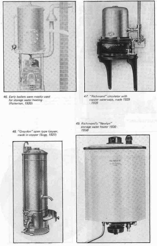
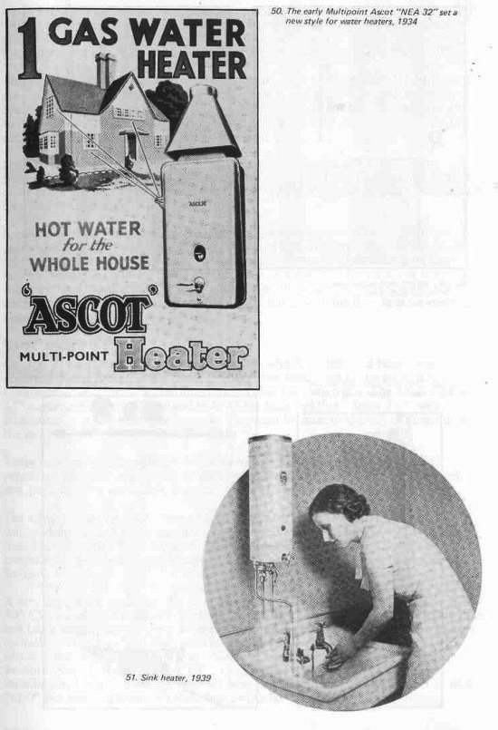
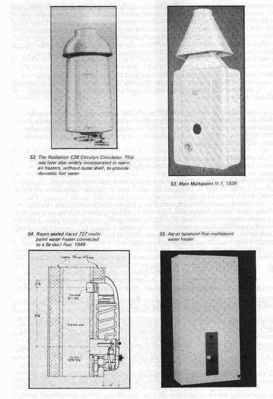
These units had a new and ingenious heat exchanger designed to obviate condensation on starting from cold and to reduce corrosion by the use of new materials. The duty of the C28 was 14 gal/h raised 80°F and the recovery rate in practice was better than the 3kW electric immersion heater. A number of compact rectangular circulators of narrow width, using leaded copper finned heat exchangers, such as the “Maxol” with contact thermostat and the Main “Isis” have also been available in the post-war period. These had a similar output to the C28 Circulyn and were widely used for storage water heating.
Many water heaters were substantially redesigned for natural gas following the completion of the conversion operation. The bimetal flame safety device was replaced by the thermo-electric and mercury vapour types and other detail improvements effected at the same time.
Ascot introduced the new types “818” and “819” room sealed multipoints with balanced flue in 1969, and succeeding multipoint units have been of this pattern by policy decision of the industry so that the risk of malfunction of a conventionally flued appliance installed with an inadequate flue system is obviated, and consumer safety still further safeguarded.
Very recently the combination of the convector gas fire with circulator mounted behind has been devised, an example being the Main “Carina E”.
Domestic water heating equipment has patently more than kept pace with changing styles in kitchen design. In retrospect the admixture of Continental practice with the British which occurred in the pre-war years was of great value to the industry. The general improvement in the equipment which followed helped retain the valuable all-year water heating load against the intense competition for many post-war years of the much cheaper electric immersion heater. A range of types to cover every need is currently available, each incorporating the expertise in design and construction of the relatively few manufacturers who have specialised in this field, some throughout the period of fifty years I have attempted to review.
13. PUBLIC AND RAILWAY LIGHTING
Gas Lighting – Pre-war and Post-war
The gas industry came into being because of the universal need for a source of light more powerful and more convenient than oil lamps and candles.
One can imagine the frustration of the engineers of the early industrial revolution as they struggled to work, perhaps on a drawing board, under a dim and flickering light. Everybody knows that it was one of those same great engineers, William Murdoch who, sent to Cornwall by Boulton & Watt to pump tin mines, lighted the office in his house in 1792 with gas made from coal by a tiny plant of his own devising. The lambent yellow gas flame met his urgent need for light.
The subsequent rapid spread of gas lighting throughout the urban areas of this country (and much of the world) has been well chronicled elsewhere, by none better than Dean Chandler in his book “Lighting By Gas”. Many thought that the invention and introduction of electric lighting in the 1880s presaged the doom of the Gas Industry, but Welsbach perfected the gas mantle and another half century of greatly improved gas lighting began, equal to or better in quality than anything the electricians could show, but in an era of growing competition. Meanwhile the other users of gas developed and ensured the future of the industry.
In the event, by the late 1920s electric lighting had become usual indoors, but in the streets and on the railways many millions of gas lamps served these islands alone, and continued to do so in substantial numbers for another thirty years. In other countries their use in the streets has continued and the gas mantle, made in still greater quantities, serves widely as a source of light in portable leisure applications using Liquefied Petroleum Gas.
A trend towards the increase use of gas lighting for both indoor and outdoor purposes and for emergency lighting is currently evident since recent interruptions in electricity supply and as relative fuel prices change. The gas mantle works exceedingly well on natural gas.
For much of the half century I have to review therefore street lighting continued as an important duty of the gas industry and was regarded by many in the industry as its most public “face”. Public lighting was pursued against the increasing electrical competition with the utmost vigour and to the last ditch by both the supply side and the manufacturers, of whom there were a number who had engaged in this field almost since its inception.
Two kinds of gas lighting were in use in our streets in the 1930s. Some major city centres and important streets were lit by Keith High Pressure Gas Lamps, originally marketed early in the century. These were supplied by local compressors through separate mains at 2.1/2 lb/sq in. This pressure sufficed to induce complete combustion by primary air entrainment only and produced an intense white light, much akin to sunlight, in long tubular mantles used singly or in groups. The lighting effect of these lamps, even by today’s standards, was excellent, but the mantles lasted only about 180 hours; frequent maintenance was necessary but often justified by the importance of their siting. They survived in Trafalgar Square, Regent Street, Pall Mall and particularly in the South Metropolitan Gas Company’s Area with the rectangular “Supervia” mantle developed by that company until the late thirties. Elsewhere in the country high operating cost militated against them surviving as long.
The majority of street lighting was carried out with low pressure gas lighting supplied directly from the normal mains without metering, with units having 10 or 12 No 2 mantles in the more important thoroughfares and progressively smaller units towards the outskirts, where two or three mantle square lamps lit the suburbs, often with the smaller No 1 size mantle. Each No 2 mantle burnt 2.1/2 cu ft of gas of calorific value 500 Btu/cu ft, and there were commonly 35 or 40 lamps per mile, mounted at a height of 10-15 feet, and at greater heights in the city centres. Although many lamps were operated by clock controllers, these required winding every two weeks and often resetting to suit the change in the hours of darkness, and the lamps required regular cleaning and very occasional overhaul or replacement after an accident. This considerable task was carried out by specialist staff, often under the control of the Gas Companies’ Distribution Departments, or in the large companies a separate Public Lighting Department, as also was the case with the municipally owned gas undertakings.
The Gas and Electricity Companies were consulted by the local authorities to tender for perhaps 15 or 25 year contracts for new or improved lighting and each manufacturer then competed for the acceptance of his own equipment. Frequently trial installations some hundred of yards long were erected by tie companies and the manufacturers for comparison, by measuring the horizontal illumination produced by each system at the British Standard test point on the kerb between the lamps. Many nights passed in this way all over the country come to my mind, occasionally convivial, sometimes up the ladder in the rain trying to improve matters. The public lighting engineer in those days had little chance of regular sleep and incidentally was invariably the subject of much public curiosity and advice – a colleague Vivian and I working in the middle of Tower Bridge about 1937 even attracted the attention of the police as suspected members of the IRA.
I have presented this general picture of the lighting scene because to many people in our industry the discipline will be outside their experience; today few indeed are called on to practice anything other than routine maintenance or replacement of gas lighting. With the invention in the 1930s of the electric discharge lamp, giving eventually three times the light for the same power as a filament lamp, the electrical industry finally began to triumph over gas lighting in our streets, albeit often with strange colours and stranger looking lanterns.
I have spoken of competition to the last ditch – rapid engineering development took place in gas street lighting equipment during this final period to support the aim of the Gas Companies to provide, where appropriate, lighting which was a credit to the industry and a valuable contribution to public safety.
The design and construction in 1934 of a triple-mirror photometric installation in Sugg’s lighting laboratories, my own first task in the industry, followed by the erection of a light integrating cube, permitted the rapid and accurate assessment of burner and lantern performance. These rather complex “tools” were used to design and test new gas lamps having directional reflectors integral with their design. These new lamps, with 10 or 12 mantles, initially for a mounting height of 22′-25′ for main road lighting, had a maximum candle power some three times that of their predecessors, but more importantly this was emitted in a very wide beam at the most effective angle, some 10-12 degrees below the horizontal, and this vertical angle was adjustable to allow for gradients and the nature of the road surface. Many miles of such lighting were erected, all over the country, including Chelsea Embankment and the Southend Arterial Road, and the new lanterns greatly improved the lighting on London Bridge and Blackfriars Bridge, and in main roads in Bombay and elsewhere abroad.
This development kept a gas foothold in the lighting of main roads (“Group A”), but the majority of lamps were in the side streets. Again it proved possible to greatly modify the distribution of light from a 2-4 mantle gas burner. This was done in a unit of small size and purely functional design, mounted on a swanneck of suitable height, so that old lanterns could be replaced in an hour and the extra mounting height called for by the then current Ministry of Transport requirements was attained at the same time to produce “Group B lighting”. In this lantern only the lateral angle of the reflectors was set at the time of installation to suit any bends in the road; three or four reflectors were used at Tee junctions and cross roads. Again, very large numbers of these lanterns were erected, many on new housing estates, where concrete columns embodying a housing for the clock controller were often used.
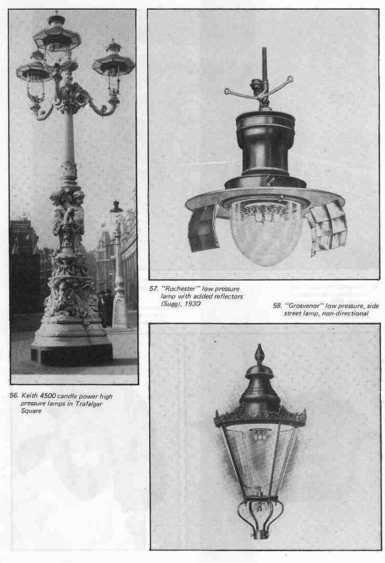
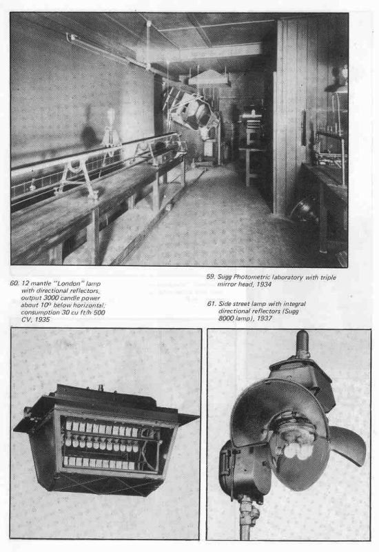
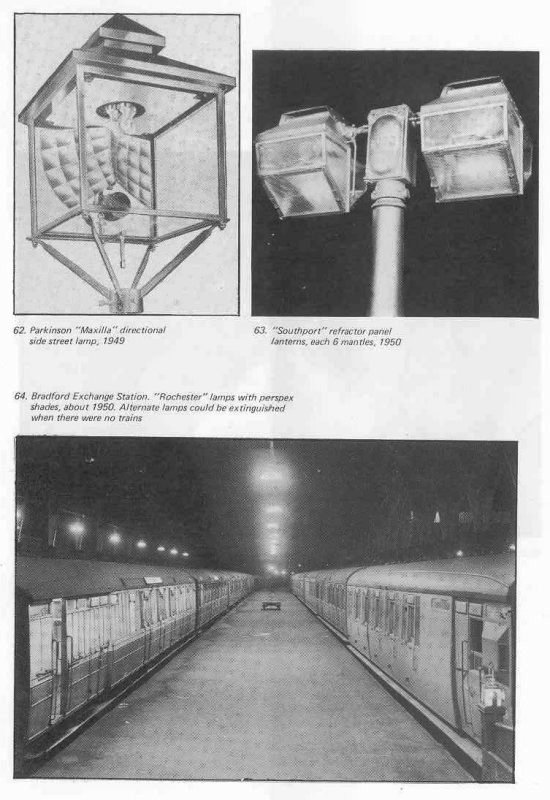
Thus by 1938 gas street lighting equipment was in good demand and many long term contracts were in operation; the process of modernising the old lighting was in full swing. The industry was able to comply completely with improved British Standards and MoT requirements and some four million gas lamps lit much of our road system with hundreds of thousands more on the railways. Several manufacturers had produced new designs of street lamps, notably Parkinson (W.I.G. Davey) and Willey. A successful counter-attack against the competition could be claimed, not least because two major manufacturers of electric street lighting equipment, and several large cities and gas companies had purchased the Sugg photometric equipment with which the attack was mounted. The revered F.C. Smith of Watson House installed this equipment at Fulham; he also presented many papers on the advantages of gas for lighting to learned societies.
With the onset of war and the end of street lighting the Sugg laboratory was switched to designing the “moonlight” effects permitted for essential services such as railway yards. Instead of measuring hundreds of candlepower, fittings were produced which could be inserted into existing lamps where required giving hundredths of candle power in controlled distribution to wartime British Standards.
This problem was solved rapidly for both gas and electric light sources after permissible levels for essential lighting had been established by aerial observation. Very large numbers of these units were manufactured to close limits of performance, with a laboratory photometric test of the tiny light output on every batch of one thousand units to ensure strict observance of the standard. My own main wartime task was to develop the use of light to decoy enemy aircraft from their intended targets, but that is another story.
By the end of the war there was a large pent-up demand for gas lamps, particularly from the railways, and abortive attempts were made to press the complex shapes of the copper lamps which had hitherto been made by spinning, then becoming a rare skill.
With increased labour costs much attention was paid to reducing the maintenance requirement of lamps by the use of 40-day clock controllers with self-adjusting tappets on `Solar’ dials, cleaning pins on injectors and improved access, and agreement was reached with the Unions to clean double the number of lamps with such features.
However, electric lamps were attended only quarterly and the writing was on the wall for gas lighting. The lighting era of utilisation, the longest in the industry’s history, can best be completed now in this narrative, for it extends as regards the development of new types of equipment only until the 1950s, although gas lamps still burn well if not better on North Sea Gas in some of our streets and parks and proudly around Buckingham Palace and the Houses of Parliament.
14. INDUSTRIAL GAS 1929-1979
Before the first World War the United Kingdom exported some 97m tons of coal out of every 300m tons annually mined. After that war most coal exports were lost, other fuels assumed greater importance and the application of gas to industrial processes began, largely by trial and error methods. Previous to this the use of gas in industry has been limited mainly to lighting the factories, where after 1900 the Selas mixed gas and air system was often used in large establishments. Gas engines were commonly used for small and medium power requirements, where steam was not available, using mains gas. (Major gas engine systems had their own producer gas plants).
Within a few years some large gas undertakings in the Midlands were supplying more than half their output to industry, where gas was used for a great variety of purposes, generally in a rather profligate way with appliances or furnaces which did their job well but often by modern standards with low thermal efficiency. This was perhaps encouraged by the low prices quoted for gas in the laudable effort to extend its virtues to industry. Further south, the electric lamp manufacturers had found that the use of gas for glass blowing alone made possible the automated production equipment for their wares, and a large industrial load resulted here.
The Industrial Gas Engineers were a specialist race apart – experienced and ingenious and with a close liaison with the industries they served, for which they designed, and sometimes made, equipment required for a particular purpose, either through the manufacturers or in Gas Company workshops devoted to meeting the needs of local industry.
This penetration of a new field of utilisation by ad hoc methods was fostered by the readily demonstrable advantages of cleanliness and controllability of gas for many critical industrial heating processes, but to the hard headed business man costs were decisive in the choice of fuels, particularly with cheap supplies of fuel oil becoming available.
In 1927, starting from the knowledge gained at the University of Leeds under W.A. Bone, who had established the Department of Applied Chemistry in 1906 and later worked at Imperial College, the then newly opened Watson House gradually brought together the relevant previous work by the Gas Research Board with its IGE-SBGI representation, Smith, Walter, Lacey, Fishenden and others.
In 1933 the Industrial Gas Development Committee was set up, acquiring, recording and disseminating specialised knowledge through regional centres in such fields as gas furnace design, combustion engineering and industrial requirements. Some of the pioneers here were Dr Walter, Dean Chandler and W. Dietrichs.
Standard designs of muffle and pot furnaces were evolved in conjunction with the manufacturers, such items being of wide application in industry, with notably increased thermal efficiency and of workmanlike appearance. It is notable that the GLC muffle furnace, originated in 1932, continues to find ready application today.
The availability of the basic scientific knowledge to the body of already experienced industrial engineers enabled them to provide many industries with sophisticated equipment often using large quantities of gas, sold at special tariffs, for purposes where critical control of the heating process was particularly needed.
By 1936 in the Sheffield steel industry, gas was for example in use for the continuous annealing of stainless steel strip, for the bright annealing of non-ferrous metals and for steel hardening in a controlled atmosphere. Despite the availability of coal at 13/- to 17/- per ton (65p-85p per ton), gas at 1/- per 1000 cu ft (1p per therm) competed effectively even for the conversion of existing coal fired equipment.
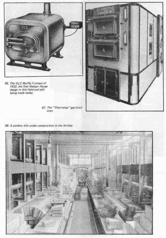
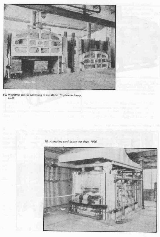
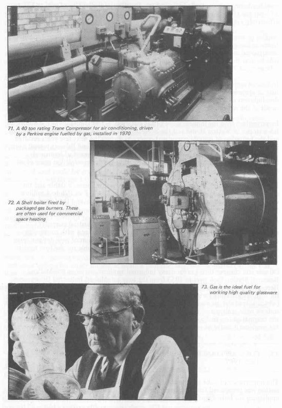
Similar progress was achieved in the Welsh tinplate industry with gas fired annealing furnaces having recuperators, and in the Potteries; where one tunnel oven had been constructed in 1932, there were over 200 by 1950. These ovens had regenerators each side to heat the ingoing air and although up to 300′ long operated with a thermal efficiency of 70% under automatic temperature control.
Industrial applications of gas obviously played a very essential role in the manufacture of armaments during the 2nd World War, but there was little opportunity for the development of the technology – immediate use of existing knowledge best met the needs of the nation.
Investigations into the industrial use of gas restarted in 1946, notably at the industrial laboratories of Watson House and the S. Metropolitan Gas Company and at Bradford, and the initiation of outside consultant contracts during the next few years resulted in some notable installations, such as the 400′ long Huntley and Palmers biscuit oven. This was a period of steady evolution, including the development of improved instrumentation, against a background of increasing gas prices while the price of oil reduced.
In 1950 the “Hypact” burner was developed which was immensely stable and the design of which could deal with a range of throughput form 1 cu ft/h to 1 million cu ft/hr. By 1960 some 50,000 of these were serving industry and the foundations were laid for the modern high intensity burner.
The need to produce still higher temperatures for special industrial purposes encouraged further designs using the recuperation principle, and with continuing demand the available equipment was expanded by the addition of new designs, more efficient than its predecessors, attractive in appearance and able for the first time to attain, if required, temperatures up to 2100°C.
Oil was still cheaper than gas for many industrial applications when the Midland Research Station took over in 1953 from the long established Industrial laboratories. Here work proceeded on many subjects such as the recuperative burner, the hot gas pump for high temperature carburizing and in 1967 rapid melting furnaces for aluminium (which halved the gas consumption previously necessary). This was the springboard for today’s wide scale use of gas throughout industry. MRS and its predecessors changed the original ad hoc methods of utilisation in this field into a science, so that whatever the problem it could be solved with confidence on the drawing board.
15. COKE APPLIANCES 1929-1967
The importance of coke sales to the Gas Industry during the long era of coal carbonisation was recognised from the beginning. The testing and approval of coke burning appliances for both domestic and industrial purposes was initiated as far back as 1913
under the direction of the London Coke Committee, formed by Mr (later Sir) David Milne Watson from the then eight London Gas Companies. This committee became the London and Counties Coke Association by the inclusion of Gas Companies covering the South of England. The association issued an approved appliance list as early as 1937. Approval was later transferred to the National Federation of Gas Coke Associations, on the appliance side of which the Ministry of Fuel and Power was represented. On nationalisation, the Gas Council Coke Committee was formed with sub-committees to carry on the work on appliances.
For almost 40 years of the period I have to review the Gas Industry sold some 10m tons of coke per annum, representing perhaps one third of its income. Typically each ton of coal carbonised produced approximately 10 cwt of coke and about 70 therms of gas (14,000 cu ft/500 CV gas).
Prior to 1920 most coke was used in industry, mainly for steam raising (sometimes in power stations) and in furnaces and large central heating and hot water installation where ungraded coke including coke breeze was suitable.
For domestic use graded coke of controlled quality was required so that it could be kept alight for long periods at low combustion rates and a great deal of attention was devoted by the industry to the provision of such a fuel. In practice about half the coke produced could be graded and sold for this market and the small coke boiler became very widely used from 1920 onwards.
In 1935 British Standard 758, the first on domestic appliances, was issued by the cooperation of the fuel interests, the boiler makers and the users. Boilers were specified with combustion chambers as small as half a cubic foot and capable of being kept alight overnight without forming clinker. Both cast iron and welded 3/16th inch thick steel construction was used. The main purpose of these boilers was hot water supply, sometimes with one or two gravity circulated radiators and the storage tank was of 35-40 gallons capacity. The efficiency was reasonably high and the 9″ x 9″ brick flues to which most boilers were connected could sometimes suffer condensation trouble where they projected beyond the roof; the need for a lined flue was forecast. Gravity feed coke boilers for larger domestic heating purposes reached the market about this time. Some of these had thermostatic control.
The circular boilers with water space all round the fire had an efficiency of 50-60%; other types had horseshoe shaped water space and an openable front door to give radiant heat when required in the kitchen. The smallest of these boilers, for instance the “Glow-warm No 1”, with one radiator connected and heating water for a bath used about 1/4 cwt of graded coke nuts per day, ie 5 tons in a year. More elaborate boilers were provided with automatic controls to limit the water temperature and thus reduce the deposition of scale. The hot plate often provided on top could be used for simple cooking operations. Stoking was typically required every ten hours and cleaning of the fire once a day.
A notable result of the widespread use of these boilers and other coke appliances was the reduction in the smoke emitted from chimneys.
Another contribution to eliminating coal smoke was the development in the early twenties of the open grate to burn coke often with a hot water supply boiler behind. These grates in their original form had a radiant efficiency of about 25% but required stoking every few hours.
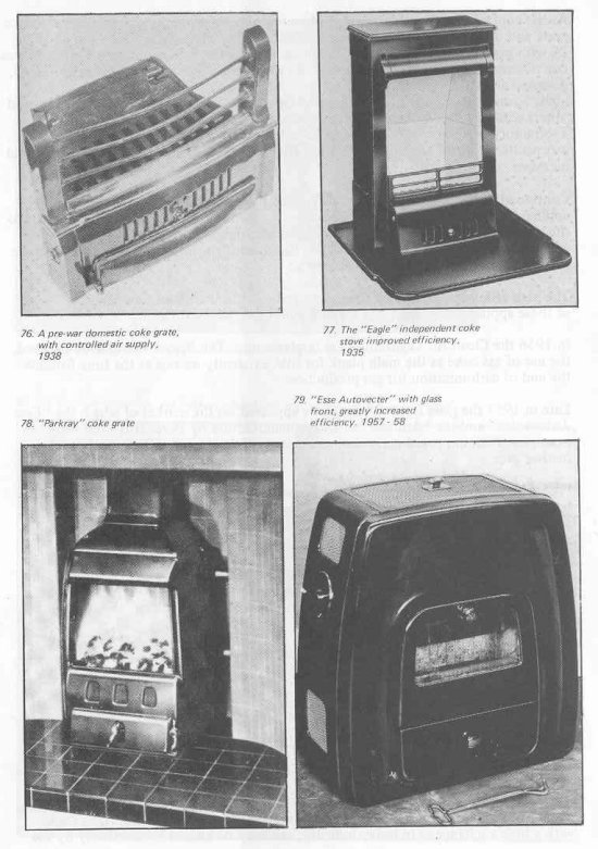
As the control of coke quality and grading improved many examples of the open coke grate and other coke appliances were marketed. The “Metro” Gas Coke fire of 192428 with gas ignition effective in 15 minutes, sold by the S. Metropolitan Company was one of these widely used for many years in their area of supply. The “Fulham” grate, designed about 1938 and made by Radiation and Eagle solved the problem of overnight burning by the use of an air supply damper with ground surfaces. This grate and others with this feature became very popular after the war. The “Fulham” grate had a refractory brick at the front and sealed ashpit, so that with the new damper there was positive control of primary air flow. The radiant efficiency was 34%, a substantial increase.
Continued development effort had also raised the efficiency of other coke burning appliances. By 1946 the domestic boilers with open fire front transferred 50% heat to the water and the closed “heating type” had reached 60% to water. The overall efficiency of both types was about 70%. Thermostat control was introduced on these smaller appliances in 1947 by Ideal.
The high efficiency convector coke stove followed in the fifties; the “Parkray” series of these appliances became well known, as did the “Hurseal Hurdapta” of 1955.
In 1956 the Clean Air Legislation was implemented. The Beaver Committee assumed the use of gas coke as the main plank for this. Evidently no one at the time foresaw the end of carbonisation for gas production.
Late in 1957 the glass fronted coke stove appeared on the market of which the “Esse Autovector” and the “Arnhem” of Dutch manufacture by Borchardt were early examples. With improved control of secondary air the overall efficiency showed a further gain.
Probably the final development of the domestic coke appliance was the “Redfyre” boiler with gravity feed hopper, finned boiler and a small electric fan for the inlet air controlled by a thermostat. This sophisticated unit of clean rectangular design was marketed in 1962-63.
The extent to which gas coke contributed to the heating requirements of the nation can be judged by the aftermath of the end of carbonisation in 1967. In 1970-71 the severe shortage of smokeless fuel resulted in the necessary abolition of 870 smokecontrolled areas.
16. RADIANT HEATING PRE-WAR AND POST-WAR
In the 1920s indoor gas lighting designed to produce a good working light was estimated to provide one third of the space heating requirements of such factories as cotton mills, where the increased humidity due to its use was also beneficial to the spinning process.
Many other buildings, intermittently used, such as churches and schools, or those with a high airchange as in heavy industry, can only be heated economically by the use of radiant heat. Even open loading bays can be heated by this means, without raising the air temperature.
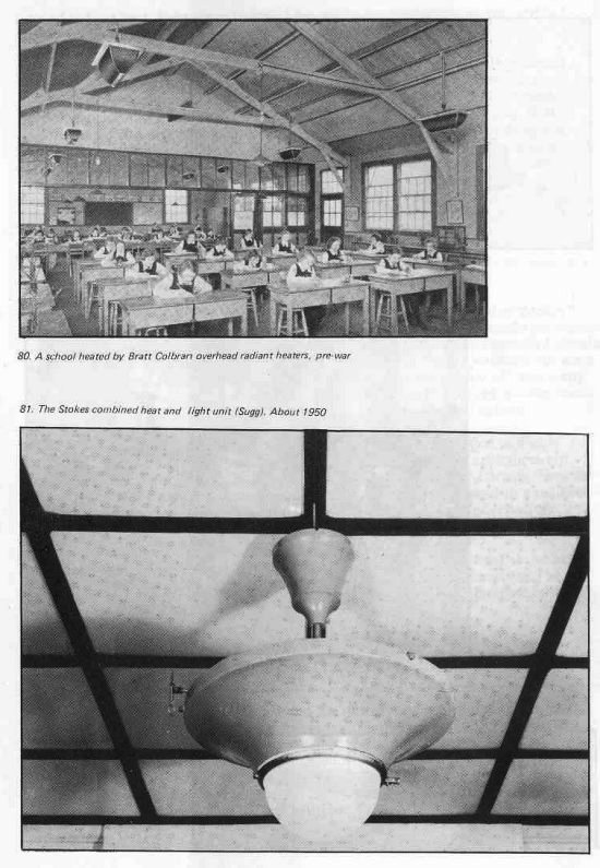
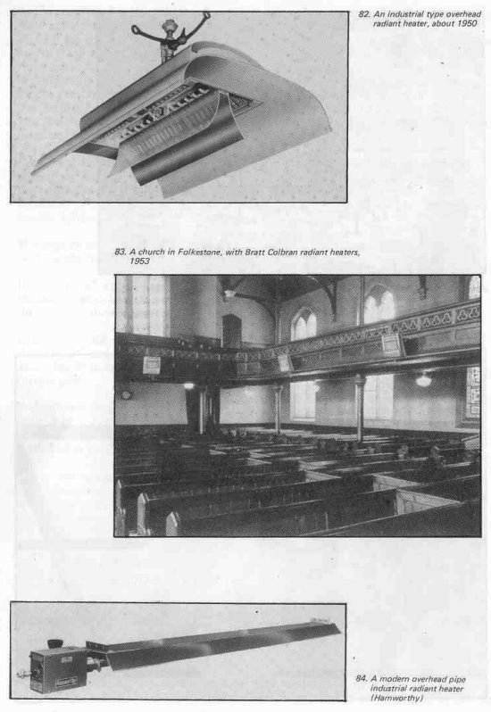
However, like light, the radiation of heat is rectilinear, and any obstacle produces a “shadow”. Nevertheless excellent examples of this form of heating were extant in the decade before the war and several manufacturers specialised in providing a range of equipment suitably styled and finished to meet the variety of applications. Both wall mounted and suspension units were available and the technique for designing installations to the desired standard was fully developed, the spacing, mounting height and output being the main parameters. Names such as Bratt Colbran and Arthur Docking of Radiant Heating Ltd come to mind in this connection. Remote control and ignition systems were often necessary for these heaters and were generally similar to those used for gas lighting.
The units often consisted of a jetted burner from which the products passed between a refractory brick and the outer shell, but some had radiants more akin to those of a gas fire, so that they emitted a cheerful glow.
I had personal experience of the design of one only of these devices, the “Stokes” combined heat and light unit, in which the heat source was a 10-12 mantle gas burner enclosed in a glass globe. The products from this passed between an enamelled circular radiating surface and a firebrick. These units were made in limited numbers but were evidently very satisfactory. One consumer asked for a further supply of them many years after production had ceased and was prepared to pay the cost of making them. I believe he used them in a dance hall in Wales, which he wished to extend.
In post-war years the “Schwank” ceramic radiant panel was developed to a high degree of efficiency and was employed in multiples in a variety of appliances not only for space heating but for industrial process work, such as paint drying. Here the combustion of the gas-air mixture raised the front surface of the panel to a red heat and gave an attractive appearance, often supplemented by the use of reflectors around the panels.
Recently the flued forced circulation radiant pipe heater with reflector above has become prominent for industrial purposes. Whether or not this principle can be extended to other purposes where radiant heating might best be employed remains to be seen.
17. PROGRESS IN DOMESTIC INSTALLATION PRACTICE
Today we tend to take almost for granted the security against leakage of the gas carcass and the associated appliances in our typical modern house. Fifty years ago this was by no means the case – a great many dwellings had lead or “compo” pipes and I have, much later than this, been present when one medium sized gas company received 200 reports of gas escapes in one day. Added to this was the ever present risk from the push-on rubber connectors used with flexible metallic pipe to transmit a toxic gas, roughly half of which was hydrogen.
Many other essential ancillaries to the domestic use of gas and none more than flues, have been the subject of much progress since those days in the interests of the consumers’ safety and convenience.
Starting at the meter, the reduction achieved in the size and weight is vividly shown by the illustration, which shows examples from this century dating between 1927 and 1978. An important factor in this successive re-design has been the development of improved diaphragms, both in natural leather and in polymer materials, capable of performing for many years their very essential duty. Today the meter has so shrunk in size that it and its main cock can be mounted in a box in the thickness of a wall with outside access, to which the service pipe is lead without entering the house, with many advantages in safety and in facilitating the reading of the meter.
The plug-in gas connector, as originally made for portable appliances and gas pokers, had 1/4″ BSP entry and the action of inserting and turning the plug opened the gas way and vice versa. Some models had a separate cock in the stem for adjusting the supply, and others were flush mounted neatly within the wall surface.
Two forms of seal were used, the plugs not being interchangeable. The design favoured by the Gas Light & Coke Company had a metal-to-metal cone and matching socket, the S. Metropolitan Company type had a “rolling” rubber ring within the plug which fitted over a spigot when the plug was inserted in the socket. Both types required very accurate manufacture and the arrangements for production, quality control and inspection were of a very high standard. Very large numbers of these connectors were made for some twenty years by several manufacturers and the use of the push-on rubber connector was finally eliminated. In post-war years the more compact “Simplex” plug-in connection of “straight through” design was evolved by Sugg and made by several manufacturers. This had a cock completely interlocked with the action of inserting or removing the plug. The use today of plug-in connections of different designs and larger bore for gas-cooker services is an interesting example of the value of this concept, which is employed in many fields of industry.
The most important development prior to the war was undoubtedly that carried out at Watson House on the correct design and installation of conventional flues by Masterman and his colleagues.
The subsequent provision of flue components of all kinds and the dissemination of the British Standard and the general increase throughout the industry of knowledge of this subject was a major factor in eliminating the malpractices of earlier years, with their attendant risks to the safety of the consumer and the reputation of the industry. This has culminated since the war in the development of the ridge terminal which is so inconspicuous that conventional domestic flues can be sited with much greater freedom and with the approbation of the architect.
The disposal of the products of combustion has been and continues to be a preoccupation of all in the industry concerned with utilisation and much development work has been devoted to this subject and several concepts have been revived and put into daily use and new methods devised.
Amongst the earliest of these was the balanced flue, made practicable by Davis about 1935 although originated last century. The Davis balanced flue convector, made in cast iron, was intended for use in garages where there might be an explosion hazard from petrol vapour. This type of flue was subsequently adapted for such convector heaters as the Radiation “Balancia”, with a circular concentric arrangement of combustion air and flue gas passages, and the “Sapphire Convector” designed at the Central Laboratories, which had rectangular passages. The imported “Drugasar” in its earlier form employed a “balance box” and grille set flush with the outer face of the wall, with separate circular pipes to lead in the air and lead out the products. All took much development, with long periods of trial because of the very great range of wind conditions over which the balance had to be maintained within the limits necessary to ensure correct combustion. The advent of “wind machines” in laboratories speeded this process and was particularly valuable when the design of balanced flues became necessary for Natural Gas, so much less tolerant to any recirculation of products in the combustion air.
The balanced flue has been applied to most types of appliance with great advantage to safety and compactness of installation; even gas lamps were balanced flue devices. In general, developing and making a room sealed appliance is more difficult and costly than the conventionally flued type, but on safety grounds alone can be fully justified.
A development after the war which proved vital to the expansion of the water heating and warm air markets in the early sixties was the Se-duct flue and its variation the Uduct, for which many room sealed appliances were developed which had to be tolerant to operation on slightly vitiated combustion air.
This technique was first applied to the installation of room sealed Ascot water heaters in multi-storey flats. In later developments room sealed air heaters were added to the Se-duct and also warm air blown drying cupboards, the outlets of which were automatically isolated from the duct whenever the door was opened.
The design and use of Se-ducts for buildings varying from one storey (the post-war “prefab” house with Ascot and Halcyon) to high rise flats was reduced to an exact science by Carne and T.T. White and many thousands were installed, in all parts of Britain, and also in France where somewhat different design parameters were used.
The conversion to natural gas of the types of appliance flued in this way involved increasing their tolerance to vitiation of the combustion air and was successfully achieved, usually without downrating. The development of these special conversion sets was greatly assisted by the use in the appliance makers’ laboratories of the Se-duct test rig, a vertical duct through which controlled volumes of air of adjustable vitiation could be passed, with the appliance to be tested installed on it.
The Se-duct proved a remarkably good and completely safe method of solving the problems of product removal and combustion air supply.
This section would be incomplete without reference to the improvement in the public image of gas and the safety of consumers which has resulted from the incorporation of improved means of ignition in all types of appliance and the great deal of attention given to controls and safety devices of all kinds. After the war any young couple setting up house almost automatically chose electrical appliances because it was the “age of the push-button”. The idea of using a match to light gas, even occasionally, was regarded by many with some fear. The two disadvantages of combustion, the need for ignition and the disposal of products have been completely overcome by the progress of the last fifty years.
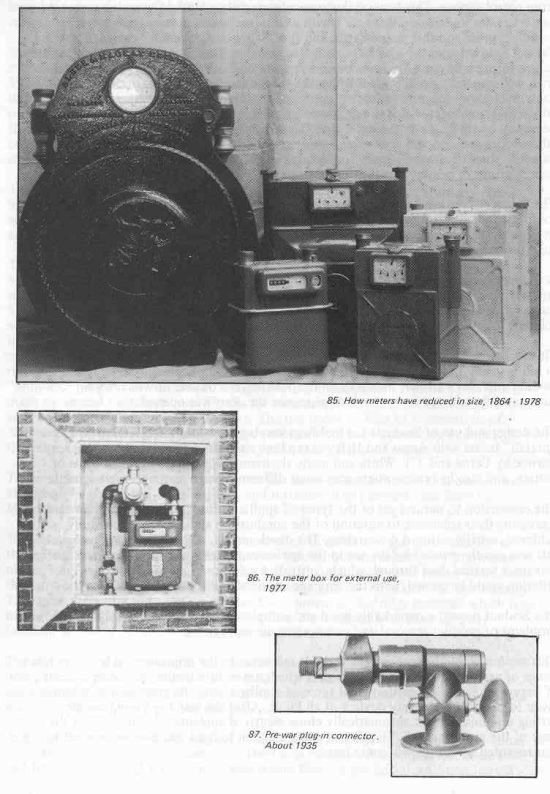
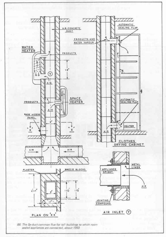
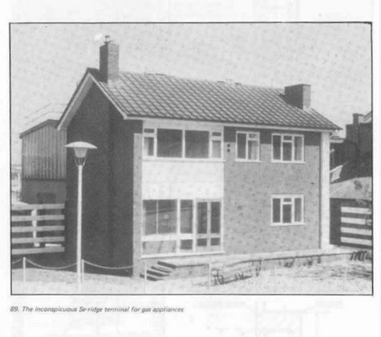
18. INCINERATION PRE-WAR AND POST-WAR
The use of small incinerators in substantial numbers for the destruction of insanitary material in hospitals, factories and shops, etc, dates from the early thirties. The Sugg appliances, in mottled enamelled finish, were later fitted with dashpot timing devices, so that after opening and closing the charging door to put in the waste, the aerated burner continued to operate for some twenty to forty minutes to ensure complete destruction. It was possible to adjust the burning time to suit the nature of the load; the burner consumed 25 cu ft/hr (500 CV) and the appliance was fitted to a 4″ flue without draught diverter. Some other manufacturers produced smaller and larger types, including Jackson.
In the pre-war years the appearance of these appliances was improved and the timing device made more readily adjustable. The combustion chamber was lined with firebrick and with a cast iron grate and an agitator to break out the ashes they became fairly widely used, a limitation being the need to provide an individual flue extending to the top of the building in which they were installed.
Shortly after the war the flue problem in tall buildings was overcome by the development by Vivian of Suggs and NTGB HQ Division of a forced extract common flue system, the design parameters of which were investigated by Watson House and published in a booklet.
Subsequently a great many large buildings were equipped with incinerators in every toilet, the equipment by then having been much improved in appearance. These had a burner rated at 12.1/2 cu ft/h (500 CV).
The fan for the extraction of the flue gases was mounted under cover on the roof of the building, with a flow detector which locked out the main burners of the incinerators, but not the pilot flames, if the fan was not operating, or failed.
With flush mounting of the incinerators and concealed flues, the design of this equipment reached a very high standard and for some years contractors bracketed this type of incinerator installation with the other services they provided in major offices.
An example of a block equipped completely in this way is the Shell Building in London. No visible smoke is emitted from such installations.
In the fifties much detailed work was carried out with the hospitals on the destruction of soiled dressings to prevent cross infection between wards and a larger unit of suitably clinical appearance was made by Sugg, sized to deal with a 32 bed surgical ward. I recall some interesting tests on the disposal of swabs soaked in ether. I rapidly consumed half a bottle of ether on cotton wool while a dozen or so hospital staff stood well back behind me – not even the slightest explosion occurred, rather to their disappointment, I thought.
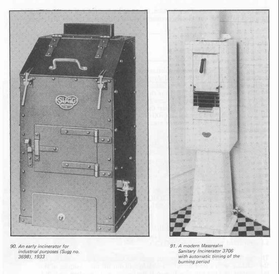
After all this, the risk of cross infection was discounted by the doctors and the principal use of the small incinerators for hospitals proved to be in nurses’ homes.
In the sixties a British Standard was compiled for small incinerators because the electrically heated units necessarily used by the Ministry of Works for Service establishments remote from gas mains did not consume the waste completely. There was never any such trouble with the gas models and some LPG versions were made for such purposes.
The small incinerators are still made, but the principal reason for their use has gradually disappeared with progress in other directions.
I have mentioned Sugg in this connection, but several other firms including Radiation and Victor contributed to the development of this type of appliance and its market. Some incinerators of the “smokeless odourless” type were also imported from America, where they were at one time very widely used for domestic rubbish destruction in areas where there was no organised collection. These incinerators had an “after burner” which raised the temperature of the products above 1400’F, effectively oxidizing all smoke and smell. I have seen one lit in a room without ill effect, visible or otherwise.
Before this principle was known here, I carried out lengthy experiments on the destruction of household rubbish at my home and I can vouch for the enormous volume of smoke which can be produced from one incinerator by the “runaway” combustion which occurs when the material finally dries. This happened in the early hours of a moonlit night and filled the valley of the Brighton Road at Purley for miles level with the top of the hills.
Nevertheless, many householders have installed incinerators (not subject to this effect) and have benefitted by their dustbins containing only empty tins and bottles.
Domestic waste today has a considerable calorific value. Some authorities recover this in central plants and there has been at least one attempt to design a domestic heating appliance able to make use of this fuel in association with gas and provide the benefits of incineration at the same time. One day this may even be cost effective.
19. TOMORROW? — A CRYSTAL BALL (Don’t forget this was written in 1979)
Having attempted in the foregoing to set out aspects of gas utilisation during the last fifty years, I must now look forward towards 2029 when our Institution will celebrate the centenary of the granting of its Royal Charter.
Seldom can there have been a period in which the conditions on which to base prophecies of any kind have been so fluid as they are today. Extreme changes have occurred over the last few years in the relative costs of the various forms of energy on which our civilisation currently depends. The projected depletion of world oil and natural gas reserves within a comparatively few decades has initiated a search for alternative sources of energy, some of which may hopefully make a useful contribution to our needs during the next century.
The nuclear programme which at present alone offers a reasonable prospect of cheap electricity generation on a wide scale is, I believe, at some risk, at least in the form to which it has so far been developed. One or two accidental “excursions” of radio-active material will so strengthen the public fear of this technology that Governments may be forced to delay and reappraise the deployment of nuclear fission. Whatever the outcome, I believe the cost of electricity generation may well exceed the present hopes of that industry. Should accidents occur to nuclear plants, only the development to fruition of the inherently safer fusion theory, at a date probably beyond the period I have to consider, will restore the possibility of electrical energy generation at low cost. Meanwhile that industry may well have to remain largely coal-based, and the consumers will continue to bear high prices for energy in this form.
Among other results of the recently intensified worldwide search for fossil fuels is the reported discovery of vast new reserves of natural gas at very great depths in the Gulf of Mexico, the so-called “primordial methane”, dating from the formation of our globe. Reserves adequate for thousands of years have been mentioned. Whatever will arise from this situation is obviously of the greatest moment to the world economy and to our industry, but I would hazard a guess that the cost and timescale of gaining this gas, wherever else it may be found, will put its practical contribution to our well-being well into next century. Let us hope that I am wrong.
Turning now more directly to energy utilisation, I find that the intensified study of the use of solar energy for domestic heating appears to have completed a momentous step forward, again in the United States, in the design of houses which, without any mechanical equipment, are stated to be self-sufficient for heating and cooling. Again the repercussions of such developments could be substantial and the fullest possible information must be sought, a matter I have in hand.
So much for the major uncertain factors in the situation in which we find ourselves. All that those concerned with the many uses of gas can do is to ensure, to the best of their ability, that the utmost benefit is obtained from the consumption of every therm and to introduce new concepts, and take advantage of those developed in other industries and other countries, as soon as they become cost-effective. Ideally, such new concepts should be well tried in district service before their full exploitation is economically justifiable. Particularly necessary is district experience on the maintenance and durability of gas equipment, probably having different and more sophisticated features than commonly in use today. Here I have in mind the rapid developments taking place in the electronic control field.
With these general observations I now turn to some of the individual applications of gas, the history of which I have outlined, and comment or hazard some thoughts for their future, although I can claim a recent close connection only with central heating.
The Gas Cooker
If I were seeking to improve the efficiency with which gas is used for cooking I think I would start by integrating the design of some frequently used cooking utensils more closely with that of the hotplate. By recessing a special saucepan of high conductivity several inches into the hotplate or raising a skirt round it I would hope to achieve better transmission of the heat from the burner to the food to be cooked and reduce the risk of a pan being knocked over by a child. The utensils would be part of the equipment of the cooker and would be sold with it. I have little doubt this idea has been tried before.
Another new aspect of cooker design may well arise from changes in houses and their construction. While a cooker provides appreciable adventitious heat gain and can make a significant contribution, to space heating in a small “low energy” home, there will be occasions when it is undesirable to allow cooking vapours and odours to permeate the house, which as I shall show later, will often have a ventilation problem, and which in any case affect decorations, especially in the kitchen. I might therefore integrate with my cooker design a facility for collecting any vapours and either reject them directly from the dwelling or through a ventilation system incorporated in the heating equipment.
The future of gas cooking and catering equipment in its present very highly developed state seems to be completely assured and no doubt steady evolution will continue and equipment be produced for new purposes as they arise.
The Gas Fire
The temperate, rather damp, climate of this country in winter and human physiology will always ensure appreciation of the comfort to be derived from a source of radiant heat, particularly if it is associated with a cheerful glow.
The convector/radiant gas fire in a well insulated house will I believe always serve our physical need for a proportion of the heat input to our bodies to be in radiant form.
I would anticipate that with the escalation of building costs orthodox chimneys will become rare in new construction and that it will be necessary to persuade builders to include precast block flues suitable for these appliances. The availability of the balanced flue version of the gas fire will be of increasing significance both from the installation aspect and its higher efficiency. I am also confident that the design of all these appliances, now so carefully studied, will continue to keep pace with changes in the style of interior decoration and the heat requirements of living rooms.
Again I find it difficult to make any worthwhile suggestions for the further improvement of a range of appliances already to such advanced concept. My own aim was at one time the design of a room sealed gas fire for Se-duct or balanced flue and this was achieved together with a district trial, but the appliance never reached the market. Now that the limitation imposed by the need for a chimney can be removed I see no other design target other than a steady increase to the optimum possible thermal efficiency. I believe it is important for the image of the gas fire that this should not be achieved by still further sacrifice of the radiant component of its output.
Central Heating
Many of my thoughts on this subject apply to heating systems using both hot water and warm air; I have therefore combined these headings in what follows.
The design of central heating systems has always been closely linked to the characteristics of houses, but major changes in the housing stock of a country occur only very slowly; the “life” of local authority houses for financial purposes is sometimes set at sixty years. The most common type of house to be heated in the year 2000 is therefore already in existence, but by that year there will also be a proportion of houses built to the improved insulation standards prescribed in the revised Building Regulations, and also “low energy houses” designed with still more insulation to attract sales, some of which also already exist. These houses will be small by present standards because of the greatly increased cost of land and building. I have seen estimates that the proportion of “improved” houses might be about 25% in 20 years time, but there is little sign at present of this being achieved.
However with marked increases in the cost of fuel there is the possibility that it could become cost-effective to substantially improve the insulation of existing older houses, almost to the point of adding another “jacket” where the walls are solid. Later houses with cavity wall construction also lend themselves to improvements in insulation. This latter process and that of roof insulation is already well in hand and with the increasing facilities available on the market will no doubt accelerate and provide a worthwhile reduction in heat loss in many of the houses built in the last 50 years.
The effect of these factors in housing construction and modification on the design of domestic heating equipment will be initially a limited but increasing requirement for appliances of lower output, followed much later by a general reduction in the requirement for the larger units.
To quantify this by examples in terms of steady state heat loss only, a three bedroom end terrace 2-storey house, well insulated, might have a heat loss of 17,000 Btu/h (5 kW) with the intermediate houses 15,000 Btu/h (4.4 kW). A two bedroom flat, with occupied flats above and below, would have appreciably less heat loss. These figures apparently reveal the need for heating appliances of output appreciably less than the current range, but I believe from some years of experience of tests in well insulated occupied houses that several other factors have to be taken into account before deciding on the output and features of a central heating system for such purposes, especially when the dwellings are relatively small.
I also look back, again to the United States, to the setting up of the Tennessee Valley Authority more than 50 years ago, basically to provide employment on a great scale. The economics of the project demanded that the many new houses to be erected should be heated by electricity generated by water power and should be cheap to operate, an unheard of requirement at that time in a country where oil flowed like water. By the courtesy of the Authority I have acquired some details of the experience with these houses, which were probably the first “low energy” houses anywhere. The insulation of the walls and other surfaces was designed to limit heat loss to 0.05 Btu/ h/sq ft/°F (0.284 W/m2/°C,ie between 1/4 and 1/6th of that of the air cavity brick wall construction which was introduced here about that time and appreciably less than the requirements of our current Building Regulations. Obviously there remains scope for energy saving in this aspect of new house design when the change to a further stage of insulation becomes cost-effective with rising energy costs, or is imposed by Government.
What else can be learnt from Tennessee Valley? The houses were of tight construction, as are modern houses here with their virtually watertight windows, and the natural air change was low, a fraction of that assumed in orthodox heat loss calculations. Three fans for mechanical ventilation were necessary in kitchen and bathroom; these were controlled by humidistats, so that the fans started automatically whenever damp air was detected and continued to work until the relative humidity was reduced to the humidistat setting.
What disadvantages did the occupants notice? If Junior left the door open in winter while moving his bicycle outside, the comfort conditions inside the house took some time to recover. Otherwise the results were good. Nearly all this I can confirm as being applicable to this country by the tests which John Milburn and I recounted in some detail in Communication 937 of 1974. In 1971 I was invited by the Greater London Council to make tests on occupied flats with the aim of eliminating the existing severe condensation and mould growth damage. Except that the heating was intermittent (a total of 30 hours heater operating time per week and the flats were smaller), there were similarities with the TVA houses. The flats, 3 stories high, were built with precast concrete sections incorporating insulation, but there were only two outside walls and there was a flat above; the winter average heat requirement was 11,000 Btu/h and the winter average gas consumption was 9 Th/wk + 2 Th for cooking. Notably the natural air change under still air conditions was only 1/a and sometimes less, and the relative humidity of the air within eg the main bedroom varied between 70% and 95%, with a weekly average of about 85%. Condensation and mould growth were inevitable.
Condensation ceased when the air change, increased in steps by added mechanical ventilation, was raised to about 1/2. The average humidity in the same room was then 65%, and air conditions throughout the house pleasant. Condensation is most likely to occur in the early hours of the morning before the heating starts. Humidistat control of the ventilation independent of the operation of the heater was therefore required. Communication 937 also defines the size and characteristics of dwellings in which such ventilation precautions become necessary.
It was probably just a coincidence but my one fan extracted about the same amount of air as TVA’s three fans. If I had relied on increasing the natural ventilation by making suitable openings to prevent condensation, wind effects would have varied the air change by a factor of perhaps 5 times the desired figure of 1h, wasting fuel, or might have reduced it below a quarter when condensation would again occur. I believe that only by the provision of inlet and outlet ducts and fans can positive control of ventilation be achieved; even apparently identical buildings vary in “tightness”. Humidistat control compensates for this by varying the volume of mechanical ventilation to give the desired total.
A further series of district trials in occupied one bedroom flats newly constructed and more highly insulated to comply with the second amendment of the Building Regulations was made recently. These flats were fitted with air heater/ventilator equipment before completion, the forced flue fan of which was operable by humidistat control when the heater was off. No condensation occurred on decorations and it could be prevented on windows by setting the humidistat lower.
If therefore waste of fuel by excessive ventilation beyond that necessary to provide good indoor conditions in winter is to be avoided, mechanical or otherwise controlled ventilation becomes a necessity in small “new generation” houses. If the degree of ventilation is related automatically to the indoor humidity, this fuel saving will be maximised and the running hours of any ventilation fan minimised
Other factors which will require attention with more highly insulated dwellings arise from adventitious heat gains from cooking, water heating and electrical appliances and occasional winter sunshine. These gains may sometimes equate the heat loss of a small dwelling at certain times of day during the heating season. The heat gain from the cooker, also the main source of water vapour, will for any particular plan of house, always be in the same place. The solar heat gain, if any, may arise on any two sides of the house according to its orientation when built. Wind chill effects may also occur on any side.
If these unpredictable heat gains are not taken into account in designing the heating system, a single room thermostat located in the living room may either switch off the heating when it is needed elsewhere in the house, or switch it on so that some rooms are overheated when they receive adventitious heat. The use of thermostatic radiator valves or individual room thermostats operating warm air dampers will provide a solution to this problem and standard equipment for these purposes has long been available. I have had many years experience of the latter form of control; it starts an air heater when any one thermostat calls for heat and stops it when all are satisfied, keeping each room or zone of the house at a temperature corresponding to the setting of the respective thermostats.
Summarising my views on the features required of a central heating system for the typical popular size 2 storey dwellings to be erected in future years, I believe we require:
- Heating units (boilers or warm air units) with an output in the range 20-25,000 Btu/h, say 6-7 kW. Although somewhat above the expected heat requirement, this will provide a rapid response on starting. Intermittent heating is likely wherever the occupants’ life pattern permits, and this margin of output will also provide for quick recovery after opening doors, etc. These heating units should have the highest possible part load efficiency on practical test down to perhaps 1/4 of full output in the hour, whether the burners are controlled “on/off” or by modulation.
There should be a forced unbalanced flue system with flue break to serve also for ventilation by the rejection of vitiated air and water vapour from the house, with reliable flue flow proving devices. In addition to control in synchronism with the operation of the heater burner, the flue fan would operate when the heater burner is off if the humidity of the dwelling exceeds the humidistat setting. This ventilation is synchronous with the occupants being asleep or absent. The more positive action of this type of mechanical flue should also permit a worthwhile increase in appliance bench efficiency. - Equipment providing a positive fresh air intake up to some 4000 cu ft/h whenever the heating system is running, preferably discharged warm into the dwelling to avoid draught effects. This greater ventilation flow is synchronous with the occupants’ main activities in the house.
- Either radiators with individual thermostatic valves or warm air outlets with motorised dampers controlled by air temperature thermostats in the living room and main bedroom.
While the above at first sight rather formidable specification is contrary to my innate aim of achieving simplicity, another possibility arises other than the obvious solution of using an adaption of a warm air heater with circulator for domestic hot water. The former already has the fan necessary for the considerable intake of fresh air.
The supply of domestic hot water will inevitably, at present and for many years to come, be most economically provided by gas. The annual gas consumption for this purpose may not differ greatly from the space heating load in the highly insulated home. The simplest installation, particularly from the service aspect, would I believe, consist of a balanced flue boiler and pump supplying a dhw calorifier in a storage tank and a central water-to-air heat exchanger with the warm air outlet to the principal rooms of the house controlled by motorised dampers responding to rear thermostats in those rooms. I would expect one such controlled warm air supply to the main bedroom and one to the living room to be adequate for many types of small dwelling, because the return air circulating from these rooms at a temperature of say 63°F (17°C) will adequately warm the hall and other parts of the house in its passage to the return grille of the heat exchanger. The fan on the latter would be adequate to entrain the necessary proportion of fresh air through a small duct when the heater was working. A manually controlled register in the kitchen and spare bedroom could be added or a radiator loop if more easily installed. The humidistat controlled ventilation rejection fan if required by the type of house could be of standard 6″ diameter pattern with gravity operated shutter, set in the kitchen window.
All this equipment is currently available and it would be interesting to make a practical test. It is important that the Gas Industry should be armed now with well tested equipment for the low energy house of the future, even though the market is yet only developing. It is for this reason that I have dealt with the subject in some detail. The electrical industry is no doubt studying this market.
Looking now to the central heating equipment of the 1990s, I believe that one aim should be to become independent of the electricity supply. This has already seemed a desirable feature when interruptions of supply occur and conceivably we may reach the point where a considerable part of the operating costs of a gas central heating system is the cost of operating and servicing electrically driven ancillaries..
This I realise is a rather tenuous proposal. One idea I have in mind is that each house should have a slow moving “lung”, constructed rather on the principle of a gas meter but driven firstly for test purposes by a geared electric motor and producing without appreciable noise, a pressure of perhaps 6″ wg to move cold air readily through easily installed ducts of 2″ or 3″ diameter and any necessary length. This “lung” could be in the attic, outside the house or at the back of a cupboard. The ducts would lead to small water-to-air heat exchangers in each room where the air would be heated and discharged into the room, probably after entraining some room air. Much better control of air volume to each room and simplified duct design should be obtainable in this way. The same ventilation and temperature control features that I believe necessary for the “new generation” small houses could readily be embodied. I believe such a “lung” might also be driven by a Stirling cycle device of some kind using gas as fuel, with the controls operated by air pressure from the “lung” rather than electricity. This surprisingly, would not be a new invention. A diaphragm pump driven by a waste heat hot air engine was used in the Scott-Snell street lamp of the early days of this century to intensify the light. The lamps were on Vauxhall Bridge in London. I made one from the early drawings many years ago and it worked. It was self-starting.
Changing the “free diaphragm” concept of the Scott-Snell lamp to the “free piston” compressor introduces the possibility of the Stirling cycle heat pump. This has already received considerable attention in the United States and again eliminates the need for electricity supply at least for the pump itself. The “co-efficient of performance” of the heat pump is such that the overall output of the heating system can be several times the energy input, a most attractive concept in the current situation, but one requiring much development to render it suitable for domestic application. Once this is achieved, the heat pump should find a ready market. It bears a similarity to the compression refrigerator and this has achieved a very high degree of reliability. Here also the electrical industry is advancing (they have an easier problem) and there are already domestic models available in this country.
Condensing Appliances?
It may prove simpler in the immediate future to disregard the upper limit of efficiency set by European standards and re-examine the use of condensing appliances when operated on sulphur-free natural gas. The corrosion problems of, for instance, water heaters so thoroughly studied in the past would not arise and subject to satisfactory disposal of the products, a marked increase in thermal efficiency should be obtainable, perhaps to 95%. I did this accidentally on a small air heater in 1947 fired by manufactured gas and of course abandoned it, but the change to natural gas now reopens this possibility for the future.
Premixed Burners
Already successfully used in larger equipment such as commercial boilers, several brave attempts have been made to adapt the principle to domestic appliances.
Bench thermal efficiencies of the order of 85% are obtainable, with a notable reduction in appliance and flue size. Doubtless the practical problems so far met will be overcome in the near future on smaller scale boilers and air heaters.
Whatever the choice of systems, and there will no doubt be many more than those I have touched on, the appliance industry enters this new phase of development strongly armed with experienced and diligent engineers and in a period in which substantial investment in research and development can be made. This augurs well for the future use of gas in the heating field.
The Gas Engine
Here I introduce a subject which I believe must enjoy a wider application in the new conditions of energy supply. Natural gas is an excellent fuel for internal combustion engines, no dilution of lubricants occurs and very long periods between service can be expected. I envisage miniature “total energy” systems in which the power output would be connected to electricity for lighting etc. and the cooling water and exhaust heat applied for space heating or hot water supply. This would I think come into the Commercial or Industrial field of utilisation, with the gas turbine prominent for industrial power requirements.
I have also seen in Japan an air conditioner compressor coupled to a gas engine – a converted Volkswagen engine in this case, with air cooling. The automobile type engine seems appropriate to many such applications. I am sure this is a subject already being investigated by some part of our industry.
Conclusion
I realise that my Crystal Ball has looked mainly at central heating. In extenuation I would say that this is the subject I have lived with for more than thirty years. Part of the technology I have described is the subject of patents owned by Thorn Heating Ltd, with which company I served as Research Director for some years following the acquisition of William Sugg & Co Ltd by Thorn Electrical Industries.
I sincerely thank our President Mr F.C. Barker, for his invitation to present this paper on the occasion of the 50th Anniversary of the Granting of the Royal Charter to our Institution, and all those acknowledged below who helped to compile this review of gas utilisation.
20. ACKNOWLEDGEMENTS
Thanks are especially due to Mr W. Sinden, Director of the Society of British Gas Industries, and Mr W. Richardson, our Vice-President, for enlisting the support of manufacturers to this project, and to Mr A.J. Adam for patiently checking the script.
Many of the documents consulted are in private collections, and are not normally accessible. It is hoped that the Institution’s Panel for the History of the Industry will in due time include such collections in their record system. Until this is complete no comprehensive Bibliography can be compiled.
| Gas Equipment Companies | Contact |
|---|---|
| Agaheat Appliances (Glynwed), | J. Owens |
| Cannon Industries Ltd | |
| Chaffoteaux Ltd, | R.A.Hentsch |
| Electrolux Ltd, | M.A.Craig |
| Hamworthy Engineering Ltd, | B.R. Roebuck |
| High-Vee Heating Ltd | |
| Johnson and Starley Ltd, | K.J.Davies |
| Leisure Domestic Appliances Division (Glynwed), | J.D.Irving |
| Main Gas Appliances Ltd, | A.J.Adam |
| Massrealm Ltd, (later Sugg Lighting) | Christopher Sugg |
| Metropolitan Flexible Products Ltd, | D.M. Sutton |
| Parkinson Stove Company, | via A.J. Adam |
| Potterton International Ltd, | L.J. Coles, B.S. White |
| Robinson Willey Ltd, | R. Bennett |
| ServotomicLtd, | R. Wade, T. Anderson |
| Smith Meters U.G.I. Ltd, | J.R. Charles |
| Thorn Heating Ltd, | M.J. Soley, W. Anderson |
| T.I. D.A. Divisional Services Ltd, | Dr G.W. Culshaw |
| T.I.Creda International, | J.E.Kiddle, lately of New World Radiation |
| Brooks & Kimber, Consultants, | D. Brooks |
| Kenneth Sargeant Advertising, | K. Sargeant |
| Watson House | E.A.K. Patrick, Director; Dr A. Burden, R. Webb, Miss S. Carter |
| BGC HQ | D. Butler, Information Manager (PR), F.S. Spencer Moppet |
| Segas | A.C. Collins, R.R. Mercer, A. Munnery, T.T. White |
| Negas | J.P.Sugden |
| Midland Research Station | Dr W.A. Simmonds, M.L. Hoggarth |
| Past Members of the Gas Industry | G. Behr, J.A. Buckley, O.B.E., Dr F. Eaton, R. Hayman, A.G. Higgins, C.H. Purkis, A.W. Self, A. Seton, D.R. Wills |
| British Rail | A.R. McGibbon, lately Htg, Ltg and Ventilating Engineer, L.M Region |
| Wates Ltd | R. Pitt |
(Don’t forget that this paper was written in 1979 but I felt that these acknowledgements should be retained as a reminder of the many well known names of the industry of the time and those who helped in the provision of photos and historic details. C.S.)
Back to Contents
Copyright © Chris Sugg 2006-13
10 responses
Really enjoyed looking at that information on gas,l have worked on some of them appliances in your notes. Thank you regards bobby
Hi Bobby, thanks for your note. Many Sugg appliances lasted a very long time and I still come across unlikely ones such as a 50 year old Halcyon! Chris
In my 89th year as a retired Architect this was a wonderful read, having been involved with specifying and installing Radiation ‘LONDON’ and New World 95 & 95A (quite wonderful!) cookers and other Sugg appliances. It seems now that there are few fitters who know about how a Regulo valve actually worked and how accurate they were, or where replacements are available. In the 1940s and into the 1960s progress was pretty amazing!
Congratulations to the old world of Gas Engineers! Geoffrey Uffindell.
We have just enjoyed a conference with the title “It’s a Gas” at the Black Country Living Museum in Dudley, West Midlands. It ranged from historic to the use of hydrogen fuel cells with some great displays and of course a gaslit tour of the museum after dark. One talk was on cookers and naturally the Regulo was mentioned.
Thank you for bothering to respond and I am glad you enjoyed your ‘read’. There are still lots of gaps but it is now becoming quite a useful resource and as I sit on the Institution of Gas Engineers Panel for the History of The Industry and the Heritage Panel of CIBSE I meet a lot of old world engineers and it is always fun! Chris
Hello, I’m trying to find the hand book for a 1958 flavel spacemaster, its got an eye level grill, oven , plate drawer and bottom cupboard
Try the National Gas Museum in Leicester. I don’t know anyone who collects cookers – they are a bit bulky but the museum certainly has some!
Still got letter from a Quotation from Massrealm Ltd when you were in Napier Way Crawley, Was it Christopher Sugg who was black sheep family when it sold out i recall to English electric. although the quotation was from a K.J.Bouracier dated the 15th May 1980, and the packing advise note on my purchase was 30/07/80 M.807 /7211.
They were for a wine bar and other trendy things at time. on Sea Front at 1, Rock-an-Nore Road Hastings. The 3 off ( If i recall ) was it 3,000 candle power by gas a still there and look intact from street, in all sea front property throw as it with inclement weather.. Sadly as saying goes one ruin Cromwell Knocked about a bit, is now a fish restaurant, and the lamps have been converted to Electricity. Errrr Horrible.
Black sheep – hardly! I was the one who started again with my colleague Keith Bouracier after the original William Sugg business was taken over by Thorn Electrical Industries and moved to the north east losing all the staff who had moved down from Westminster – a step too far! We bought an off the shelf company with the unlikely name of Massrealm Ltd and we were in business. Our arrangement with Thorn was that we could only use the Sugg name for incinerators (that they didn’t want) for one year and not for heating. They never mentioned lighting which was amusing when you think that the original Thorn business was lighting! After we started making gas lamps we began to use the Sugg name for lighting and eventually registered the Sugg Lighting Ltd name.
Good to have your reminiscence it was a fun career – and I am still involved with the history of the business and helping people with their questions.
Thank you!
Thank you!