Ever since the concept of burning gas to give light, some means of control and ignition has been essential. In the earliest days with a simple open flame, a gas tap controlled the gas flow and ignition could be by a flame or possibly a spark. As you will have seen in many burners illustrated on this site, particularly as they increased in size, a permanent pilot – originally called a bye-pass, burning continually – provided the means of ignition. The gas control, however, continued to be manual, switched by a lamplighter right through the 19th century and well into the 20th.
The advent of the clockwork time ‘controller’, as it was always called, tied in with the bye-pass for ignition at last provided an automatic means of controlling the lighting and extinguishing of the street lamp. Probably the best known of the gas controllers is the one deigned by a company founded by Gustav Horstmann who was born in in Westphalia, Germany, emigrated to the UK and set up a clock making and retailing business in Bath. The clockwork gas controller was first produced in 1902 and became so popular that the manufacture was transferred to G.Horstmann & Sons and by 1904 the solar dial was patented.
These clockwork gas controllers, of which the most famous was probably the 3A UNI, were magnificent pieces of equipment in which the rotating gas cock was so beautifully honed that it could be rotated by a spring wound clockwork mechanism. The addition of a mechanism to adjust the time setting every month was followed by the famous ‘solar dial’ that was capable of adjusting the time setting every day giving the company a world wide lead.
The clockwork time controller even became the first controller for the Sugg Halcyon warm air heating appliances in the 1950’s – the first means of central heating after the war.
The 3A UNI was offered with either a 14 day clock or a double barrel spring offering 40 days. The last 40 day clocks were manufactured for Sugg Lighting to supply the City of Boston, Massachusetts, in the 1980’s. All their time clocks are now electronic although not used for gas lighting!
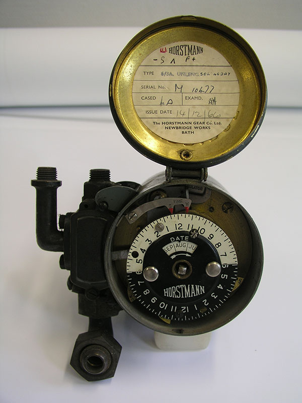
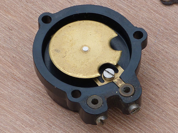
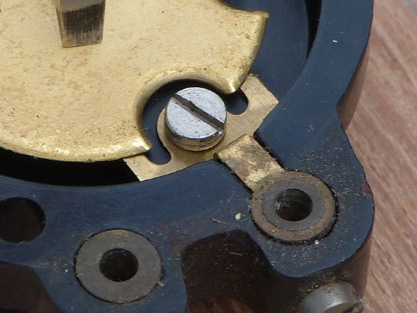
An early clock before the adoption of manually adjusted tappets.
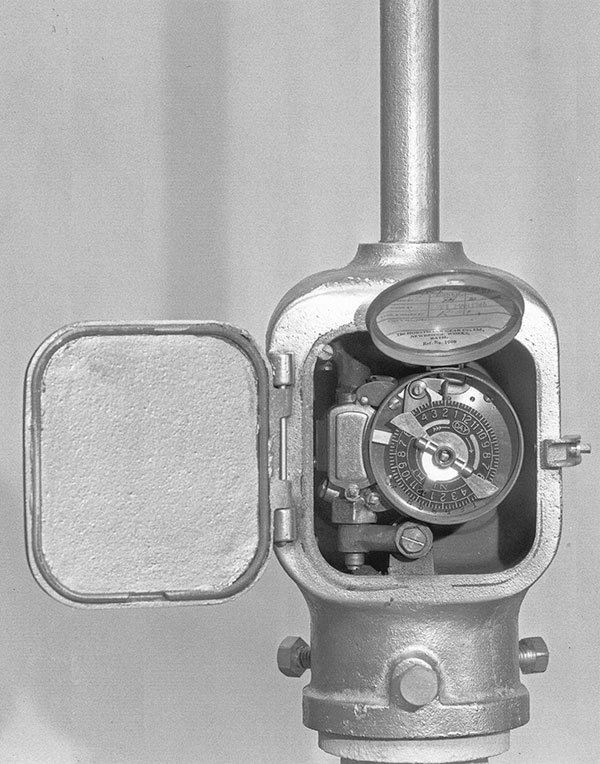
A 3A UNI with two tappets offering just one ON and one OFF switch thus a single time period. Versions with 4 tappets would provide two periods of operation so that the lamp could provide one light period from lighting up time to, say, midnight and then an early morning period from, say 5.30am to sun up. This means that the tappets have to be adjusted regularly to match the daylight. The solar dial version made that adjustment automatically.
The Newbridge Comet Igniter
Another remarkable device designed and manufactured by the Horstmann company is known as the Comet Igniter. This device was designed to replace the permanent pilot with a pilot ignition system that comes into use only when required. It is almost always used in conjunction with the clockwork controller.
The development of gas lighting ignition has a long and tortuous history! By the time the Comet Igniter was patented in 1934 the use of the permanent pilot was almost universal and worked very well with the clockwork controller. The skills required for clock making had been amply demonstrated not only with the 14 day clockwork mechanism but especially with the gas valve that was machined to such fine tolerances that the relatively modest energy available from the clockwork could open and close the valve for years. Of course the permanent pilot ran continuously whilst its actual operating time when it was igniting the gas was only seconds. The Comet device was designed to provide ignition as the gas was turned on by the controller utilising a battery operated ignition coil that was turned on and off after the gas burner was lit.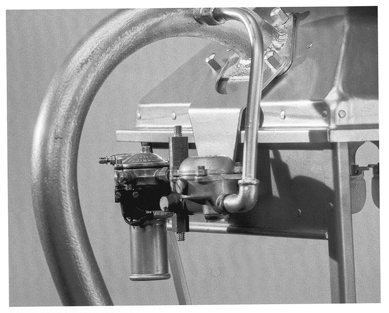
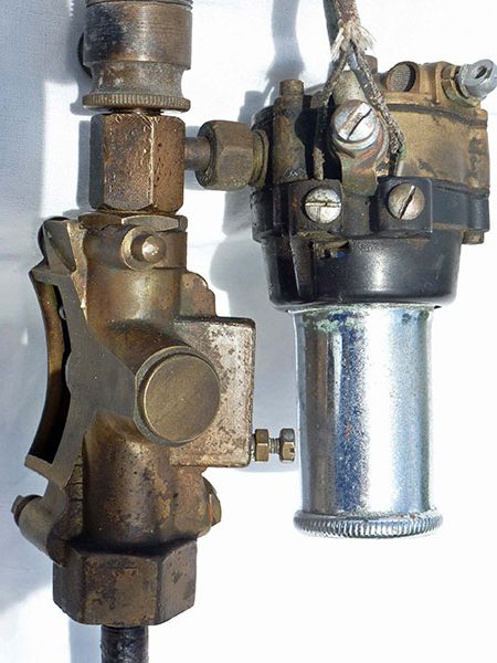
This photo illustrates the Comet igniter with its removable battery container below the diaphragm section. It is being fed by a small gas governor. This is the earlier town gas version with a single battery. See below for the later model.
So how did it work?
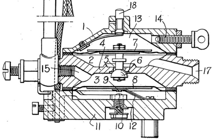
See the section drawing taken from the patent.
When the gas is turned on it enters at 17 into the space 2 below the upper diaphragm 7. It then passes downwards via the valve 6 into the space 3 above the lower diaphragm and also via passage 15 to the pilot pipe.
The space 13, above the top diaphragm is an enclosed space holding only air. As the diaphragm is pushed upwards by the gas pressure below it the air is compressed.
The screw 14 allows an adjustable bleed of air out of the upper chamber.
The gas pressure in the space 3 above the lower diaphragm presses it down and makes an electrical connection that feeds the battery power to the ignition glow coil in the pilot head, igniting the gas.
The pilot then ignites the main burner that has been fed with gas at the same time as the Comet.
As the upper diaphragm rises it closes the valve 6 progressively cutting off the gas feed to the pilot and allowing the lower diaphragm to lift disconnecting the electrical contacts.
Depending upon the rate at which air is allowed to bleed out of the top space by bleed screw 14 the pilot gas and the electrical feed time may be adjusted.
When the clock controller turns the gas off, the main burner goes out and the upper diaphragm drops slowly under gravity to its starting position. (A spring loaded version was available to allow the Comet to be used at other angles.)
Should it be necessary to start the process again rapidly i.e. before the top diaphragm has returned slowly to its neutral position, a spring loaded inward venting device 18 at the very top can be pressed to allow air into the upper space.
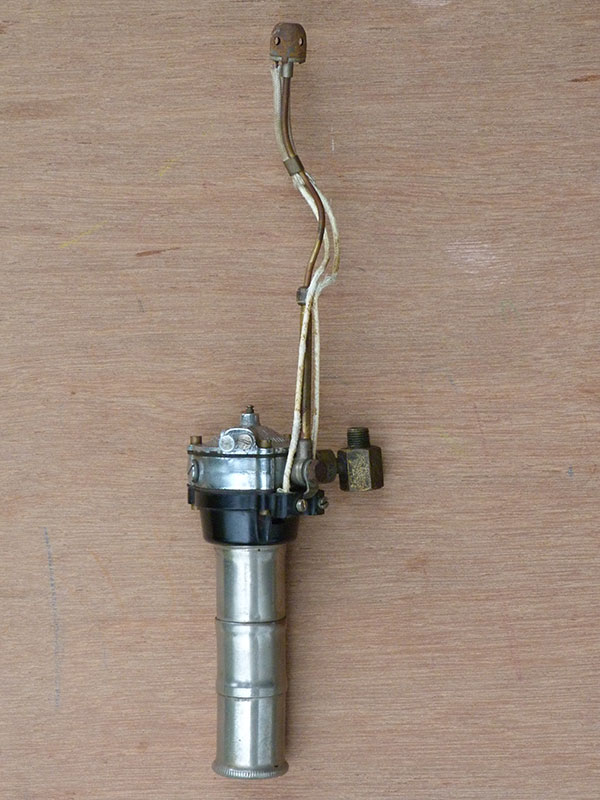
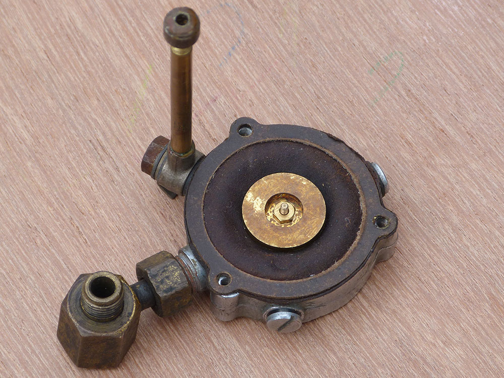
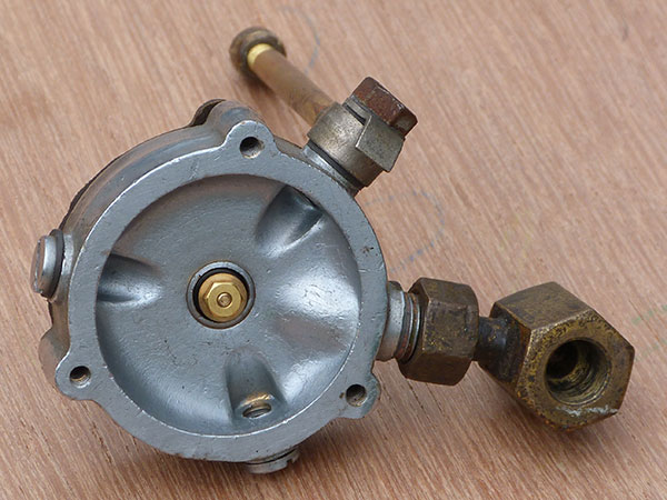
This Comet is one of the last models that was produced for natural gas with a longer double battery container to assist ignition and was loaned to me by Dorron Harper.
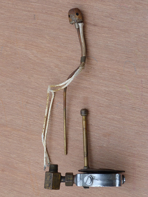
The right hand picture shows the sliding extendable pilot pipe with collet nut to lock in place to suit a variety of burners.
You can also see the external hexagonal brass component for the gas supply to both the Comet and to the main burner.
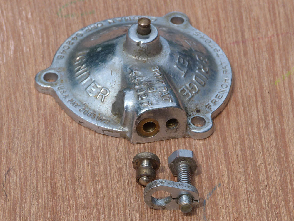
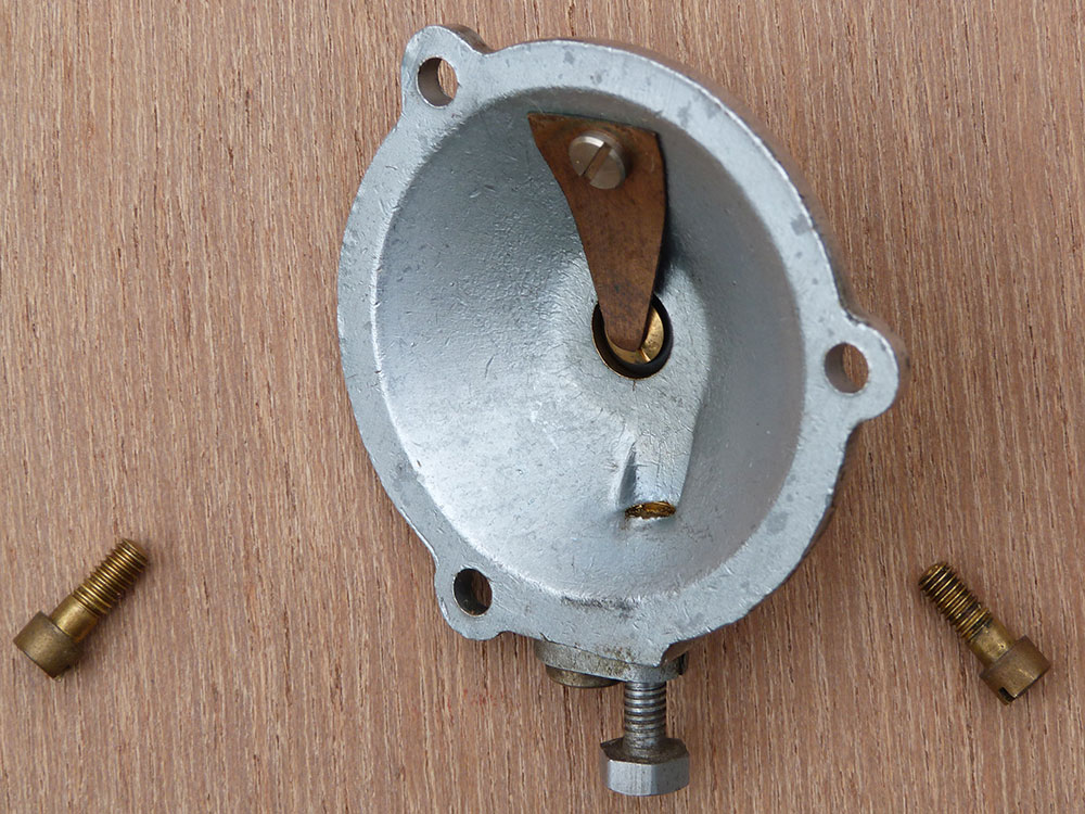
This is the top cap with the bleed screw removed. If you click on the picture you will be able to see more clearly the cast-in brass bush that the long screw runs into. The screw is machined with a square thread form to allow the bleed air to pass up the exterior.
The small fixing screw has a brass collar that fits in the larger hole in the bleed screw holder and is fractionally thicker such that the fixing screw can be tightened completely without locking the holder. This provides a slight float to the bleed screw and helps to reduce wear in the bleed hole and ensure consistency of operation over a very long time.
The right hand picture shows the inside of the cap and the small leaf spring that holds the vent button in place
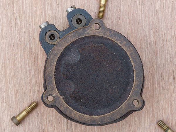
The left hand picture shows the upper diaphragm and the central brass component that is attached to the valve and the right hand picture shows the central valve and the space that is over the lower diaphragm. The three ports cast in the body allow for the pilot take-off to be in 3 alternative positions to suit the burner/lantern manufacturers requirements.
These three pictures show the lower diaphragm and, when removed, the brass plate that is pressed down onto the brass connection. It is shown making contact in the right hand picture – pressed manually. The wiring connections are clear. The battery container screws up into the bottom of this item and the central button on the battery makes contact via a flexible connection with the centre of the brass plate. The outer body of the battery container makes connection with an internal strip that is connected to the left hand wiring connection, completing the circuit when the diaphragm presses the plate down.
The picture above shows an early Comet with a single battery container attached to the outlet of the Horstmann Controller valve body. The curved part is where the clock body fits.
Other Controllers
Following an enquiry about a ‘Duplex’ controller, Dorron Harper sent me the following photos of lamps fitted with Duplex controllers.
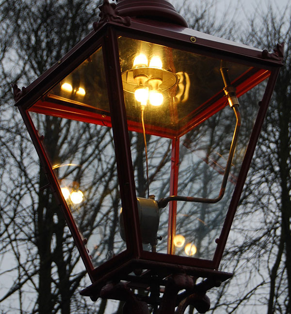
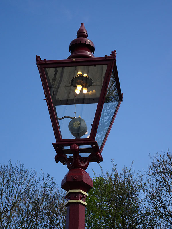
See comments below from Steven to follow the string of correspondence. Further details in due course!
22 responses
Hi Chris,
As a follow up to my separate enquiry on servicing “Newbridge” controllers, can you confirm that when the gas is turned on and so make the electrical contacts on the Newbridge ‘Comet’ ignite, the small coil remains electrically heated all the time the gas pressure is maintained, or was there some form of thermocouple that disconnected the battery supply once the mantles were lit. Without such a device, I am thinking that the advantages gained by saving on gas, would be off set by battery replacements if the battery was supplying current all the time the lamp was on.
Hello Norman,
I have asked another enthusiast who uses many of these controllers what he does regarding servicing Newbridge controllers and I will let you know. In so far as the Comet igniter is concerned when the gas is turned on it lifts the diaphragm and makes electrical contact whilst opening the gas valve resulting in a lit pilot and almost instantly the main burner. The valve then drops cutting off the gas to the pilot and disconnecting the battery so the battery life can be extended. You may have noticed that the earlier Comets prior to gas conversion take only one battery whilst the later ones have an extended battery compartment to take two. Town gas was always easier to ignite and in fact could be lit without a flame at all using a catalyst but to be certain the Comet device always used a battery operated glow coil and this needed to reach a higher temperature for certain ignition of natural gas.
Thanks for this article on clockwork gas controllers. Very interesting.
I arrived here seeking information after recently acquiring a “Duplex” controller which I can find nothing specific about online.
It looks similar to the early Horstman you pictured with no manually adjustable tappets.
I would be greatfull if you had any further info or references to this design.
It’s in a solid brass self contained case with only a single 1/4″ hole in the back for any control lever to exit.
I am curious as to how it actually worked. I presume it had additional apparatus to actually control, ignite and extinguishing the gas at the command of the clock?
Also I can only see one indicator on the dial. Is this to set dusk perhaps with other timings fixed to this?
It is labeled :-
The Duplex
Under License to Metropolitan Gas Meters
London and Nottingham
Gas Lighter and Extinguisher
Hello Steven. I wonder if you could send a picture or two to my ch***@wi****************.uk address. I have no specific information myself but have sent an enquiry to Dorron who has a wide range of knowledge across many manufacturers and will let you know.
I sent a couple of pics Chriss. Hope they arrived.
In the meantime I have also found another reference to the Duplex from the catalogue of the Ninth Annual Meeting and Conference Blackpool September 5th-8th, 1932. Which under the entry for “Metropolitan Gas Meters” gives a description of its operation.
I have also found some advertisements from the 50’s. From these advertisements I can see that there are important parts missing from mine. These include the two tappet arms and the connection to the actuating mechanism.
https://www.simoncornwell.com/lighting/manufact/mgm/archive/pl84-20.htm
Hi Steven, I received your pictures and a detailed response from Dorron Harper who included photos of lamps on the KWVR. I will add details to the website in due course but here is what Dorron said:
What your correspondent has is 50% of a Duplex controller of about 1930. As you will already have realised, the gas valve and its operating mechanism have been removed, probably to convert it to a simple time piece- note that the time pointer has been replaced after removing the gas parts. This seems to have been a common practice amongst lamp attendants, perhaps on retirement.
The valve screws onto the back and a rocking shaft protrudes into the case above the dial. It is fitted with a “see-saw” lever with little rollers on each end which ride up over the tappets and rotate the shaft, which in turn moves a shuttle valve in the gas cock body. These were the only gas controllers I am aware of which did not utilise a plug cock. A brass lever behind the dial (which remains on this one) is spring loaded to restrict the movement of the rollers to two operations per switching instead of one, thus extinguishing the pilot after ignition, and relighting it again before turning off.
The movement is Swiss, and the pinned pillars make it an earlier one, later examples having nutted pillars. Later still the movements were British, made for Metropolitan by Horstmann, and left in brass instead of the Swiss nickel plating. The movement runs for nine days, i.e. one week plus Bank Holidays and a day off for the attendant.The movements were sometimes, but not always, given a stamped serial number to match the case. However it was rare in later years to find a still-united pair! The number on this case is consistent with the age of the movement. The name “Duplex refers to the fact that there were four tappets for twice on, twice off, per 24 hours. The two extra tappets were carried behind the other two. The much earlier single tappet version was the “Simplex”.
They were commonly used, although perhaps not as much so as Gunfires or Horstmanns. Carlisle, Bradford, Leeds, and in earlier days, Nottingham are known users. There are several variations of case and valve. We use a few on KWVR- see attachments.
Thank you Chris and Dorron for taking the trouble to give such an informed response.
From this and the picture in the advertisement of a complete unit I now see how it worked.
Except for one aspect.
I mentioned a spring loaded “quick stop” lever which can be seen in the picture coming through the backplate at 2-4pm on the dial. I am wondering how this worked and it’s purpose. I can’t see it in the add either. (Nor a regulator for that matter)
I can see the occasional requirement to disable the automated process, servicing, holidays etc, but isn’t stopping the clock a bit drastic? It would then require resetting before being used again.
Also for the record, this movement actually takes a No 9 key. Despite the fact that it came with a No10 which can be pushed tight and made to work but doesn’t fit through the central boss.
Thanks again, don’t mean to derail your excellent “Comet” article Chris, please feel free to move if inappropriate. There are a few more general things I would like to ask though if there is a more appropriate place.
Dorron covers this further query as follows:
The thing Steven describes as a “quick stop” is of course the complete opposite, it is a starting device, not a stopper. A stopped clock (i.e. run down in service through missing a wind for some reason) should start again when rewound, but if it does not, a single touch on this lever will start it. Otherwise, you would have to remove the clock from the lantern and shake it.
If it takes a No.9 key then the winding square is very worn or has been filed.
Another point which comes to mind is that a Duplex has two outlets- one on top for direct burners, and one at the side for side tube ones. Either can be blocked off, although the side outlet is better for F&P than for other makes.
Dorron
Thanks again for the authoritative reply.
Now it makes sense.
I must have seen some of Dorrens work on a previous visit to the KWVR. I look forward to seeing it “in a new light” on my next visit to Yorkshire.
KWVR is very lucky to have such a talented ‘gasman’ prepared to share his knowledge so that we can use this website as a source of information for anybody interested in this period of our nation’s history!
I worked at Horstmann during the 1970s and can member being told diaphragms were made from dog skin. Also the ignition bulbs were wound by hand to give the core ct resistance. The girls doing the work had to be rotated to other jobs as it drove them “stir crazy”
Thanks for your memory of working at Horstmann. Even in my time when I started Sugg Lighting after the takeover we used leather diaphragms on a device called an ‘auto timing device’ or ATD which was used on incinerators as a means of timing the operation of the burner. I thought they were pig or cow skin but we used old stock until there was no remaining demand so I never had to buy any material! It was kept flexible in oil. Suggs had a long connection with Horstmann and even in my time they made the very last batch of 40 day clocks for the City of Boston to fit on burners that we made in Crawley. Apart from the beautifully machined gas valves on the 3a UNI the ‘Comet’ device was brilliant. You will find information on both on this site!
Found this very interesting. I was a Electician/Street Light Engineer in the 1960’s who had to maintain quite a few Gas Street lights as well as the electric ones. I hung on to a few of the time clocks for posterity. One is a monthly wind up one with auto adjust timing. This was in Romsey, Hampshire
Hello Chris, thank you for your comment. I didn’t know that electrician / street lighting engineers were faced with maintaining gas lamps. Of course they are not exactly rocket science but those 40 day Horstmann clocks with solar dials are really beautiful pieces of kit. The product of a company that was once a Swiss watch maker. At Sugg Lighting we used the very last production of the 40-day clocks to provide the City of Boston, Mass., with controlled gas burners in their famous gas lamps!
Hi. My Dad was an engineer and recently mum rediscovered a 3A uni exactly as your picture in its grey housing complete with key. Unfortunately the tappets are missing (I think I may have peeled them off when I was a child-annoying!) I have it wound up and running happily in the hall. It’s not keeping perfect time- but not bad. Runs all week! Can I adjust something slightly bring the time right? The date in the paper lid lining is 1955. My mum remembered that dad – sadly no longer with us- had somehow wired it to a radio in the early 60’s to make an early radio alarm.
Would love to get it keeping perfect time. It has a wonderful ‘tick’.
Hi Lesley, The Horstmann clockwork controllers were beautifully made and the 3a Uni was largely used to control the switching of gas lamps but also many other gas appliances. Considering they were subject to both high and low temperatures when mounted in a gas lamp and ran for 14 days between windings they were remarkably accurate. I guess that your Dad’s controller does not have the gas valve to which it is normally attached when in gas control operation so has the device been fitted with ‘hands’ to make it easily readable or are you just looking at the internal setting dial from which the tappets have been removed?
I know a man who is an expert on these clocks and will ask him if there is a means of adjusting the running time.
Dear Chris,
I am currently underway with the restoration of a Grosvenor street lamp which I believe spent most of it life illuminating the streets of Westminster and am looking for some help. I am looking to replace the pilot shroud that covers the ignition element/coil on the Newbridge Comet igniter. I am looking at the possibility of making one if this can not be purchased.
Hope you may be able to help.
Ps This website has been a great source of information and historical interest and would make for a great book.
Best Regards
Richard
Thank you, Richard. It is interesting to build a website that is designed to help people such as yourself discover a bit more about this particular area of history that has almost completely disappeared and might completely disappear along with the fight for carbon neutrality. However, there do seem to be many ways of retaining at least some of our heritage including the fact that it is possible to run most gas appliances on Hydrogen. Town gas made from coal was about half hydrogen and there are even whole villages running with test boilers on hydrogen at this moment (2021) to prove the practicality.
I will send you an email regarding your specific question. This website was the only alternative I could consider with the enormous variety of information as I could add or delete as I went and am still adding 15 years after I started!
Hi there, this weekend is nice in support of me, as this time i am reading this great informative
piece of writing here at my house.
This is very interesting, You are a very skilled blogger.
I have joined your feed and look forward to seeking more of your great post.
Also, I have shared your site in my social networks!
Feel free to surf to my site … http://mamanitascones.com
Hey there! I’m at work browsing your blog from my new iphone 4!
Just wanted to say I love reading your blog and look forward
to all your posts! Carry on the great work!